Multi Zone Indoor Wall Mount Installation Manual Models: BM09M22WM BM12M22WM BM18M21WM BM24M21WM IMPORTANT NOTE: Read this manual carefully before installing or operating your new air conditioning unit. Make sure to save this manual for future reference.
Table of Contents Installation Manual 1 Safety Precautions.................................................. 04 2 Accessories................................................................... 06 3 Installation Summary - Indoor Unit........... 08 4 Unit Parts ...................................................................... 10 5 Indoor Unit Installation....................................... 11 1. Select installation location....................................11 2.
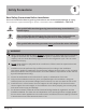
Safety Precautions 1 Read Safety Precautions Before Installation Incorrect installation due to ignoring instructions can cause serious damage or injury. The seriousness of potential damage or injuries is classified as either a WARNING or CAUTION. WARNING CAUTION This symbol indicates that ignoring instructions may cause death or serious injury. This symbol indicates that ignoring instructions may cause moderate injury to your person, or damage to your unit or other property.
WARNING 6. For all electrical work, use the specified cables. Connect cables tightly, and clamp them securely to prevent external forces from damaging the terminal. Improper electrical connections can overheat and cause fire, and may also cause shock. 7. All wiring must be properly arranged to ensure that the control board cover can close properly.
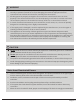
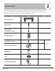
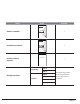
2 Accessories The air conditioning system comes with the following accessories. Use all of the installation parts and accessories to install the air conditioner. Improper installation may result in water leakage, electrical shock and fire, or cause the equipment to fail.
Name Shape Quantity SPLIT-TYPE ROOM AIR CONDITIONER Owner’s Manual Aurora Series All Model Numbers Owner's manual 1 CS78421-548-754 IMPORTANT NOTE: Read this manual carefully before installing or operating your new air conditioning unit. Make sure to save this manual for future reference.
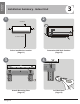
Installation Summary 3 Installation Summary - Indoor Unit 1 2 6 inches 4.75 in 4.
6 Connect Piping (Page 20) Installation Summary 5 7 Connect Wiring (Page 16) Prepare Drain Hose (Page 15) 8 Wrap Piping and Cable (not applicable for some locations in the US ) (Page 18) 9 Mount Indoor Unit (Page 18) Revised 5/14/2020 Page 9
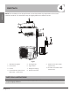
4 Unit Parts Unit Parts NOTE: The installation must be performed in accordance with the requirement of local and national standards. The installation may be slightly different in different areas. 1 2 3 5 4 6 7 8 9 10 Fig 2.1 1. Wall Mounting Plate 5. Drainage Pipe 2. Front Panel 6. Signal Cable 3. Louver 7. Refrigerant Piping 4. Functional Filter (On Front of Main Filter - Some Units) 8. Remote Controller 9. Remote controller Holder (Some Units) 10.
5 Indoor Unit Installation Indoor Unit Installation Installation Instructions – Indoor Unit PRIOR TO INSTALLATION Before installing the indoor unit, refer to the label on the product box to make sure that the model number of the indoor unit matches the model number of the outdoor unit. Step 1: Select installation location Before installing the indoor unit, you must choose an appropriate location. The following are standards that will help you choose an appropriate location for the unit.
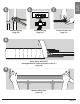
Refer to the following diagram to ensure proper distance from walls and ceiling: 6 inches or more Indoor Unit Installation 4.75 inches or more 4.75 inches or more 6 feet or more Fig 3.1 Step 2: Attach mounting plate to wall Step 3: Drill wall hole for connective piping The mounting plate is the device on which you will mount the indoor unit. You must drill a hole in the wall for refrigerant piping, the drainage pipe, and the signal cable that will connect the indoor and outdoor units. 1.
.7” Outdoor 7.05in” 4” 5.35” Left rear wall hole 2.5” 1.95” 1.95” Indoor unit outline 28.45” Right rear wall hole 2.5” BM09M22WM Indoor Unit Installation 1/4" to 1/2" 11.4” 1.45” Indoor Wall 16.8” 9.15” 7.55” 5.05” 1.7” Fig 3.2 31.6” 20.37” 5.65” 2.3” 15.45” 12.55” • Height of mounting plate Left rear wall hole 2.5” Indoor unit outline 2.25” • Width of mounting plate • Width of indoor unit relative to plate Right rear wall hole 2.
Step 4: Prepare refrigerant piping The refrigerant piping is inside an insulating sleeve attached to the back of the unit. You must prepare the piping before passing it through the hole in the wall. Refer to the Refrigerant Piping Connection section of this manual for detailed instructions on pipe flaring and flare torque requirements, technique, etc. Indoor Unit Installation 1. Based on the position of the wall hole relative to the mounting plate, choose the side from which the piping will exit the unit.
Step 5: Connect drain hose By default, the drain hose is attached to the lefthand side of unit (when you’re facing the back of the unit). However, it can also be attached to the right-hand side. PLUG THE UNUSED DRAIN HOLE To prevent unwanted leaks you must plug the unused drain hole with the rubber plug provided. 1. To ensure proper drainage, attach the drain hose on the same side that your refrigerant piping exits the unit. CORRECT 2.
BEFORE PERFORMING ELECTRICAL WORK, READ THESE REGULATIONS 1. All wiring must comply with local and national electrical codes, and must be installed by a licensed electrician. 2. All electrical connections must be made according to the Electrical Connection Diagram located on the panels of the indoor and outdoor units. 3. If there is a serious safety issue with the power supply, stop work immediately. Indoor Unit Installation 4. Power voltage should be within 90-110% of rated voltage.
Step 6: Wiring connections The signal cable enables communication and power between the indoor and outdoor units. Use 14 gauge, 4 conductor strander (not solid core) copper wire. 6. Feed the signal wire through this slot, from the back of the unit to the front. 7. Facing the front of the unit, match the wire colors with the labels on the terminal block, connect the u-lug and firmly screw each wire to its corresponding terminal. 1. Prepare the cable for connection: a.
2. Using adhesive vinyl tape, attach the drain hose to the underside of the refrigerant pipes. NOTE ABOUT WIRING THE WIRING CONNECTION PROCESS MAY DIFFER SLIGHTLY BETWEEN UNITS. Step 7: Wrap piping and cables Indoor Unit Installation Before passing the piping, drain hose, and the signal cable through the wall hole, you must bundle them together to save space, protect them, and insulate them. 1. Bundle the drain hose, refrigerant pipes, and signal cable according to Fig. 3.10.
If refrigerant piping is already embedded in the wall, do the following: 1. Hook the top of the indoor unit on the upper hook of the mounting plate. 2. Use a bracket or wedge to prop up the unit, giving you enough room to connect the refrigerant piping, signal cable, and drain hose. Refer to Fig. 3.11 for an example. 3. Connect drain hose and refrigerant piping (refer to Refrigerant Piping Connection section of this manual for instructions). 4.
6 Refrigerant Piping Connection Refrigerant Piping Connection Note on Pipe Length The length of refrigerant piping will affect the performance and energy efficiency of the unit. Nominal efficiency is tested on units with a pipe length of 16.5ft. In North America, standard pipe length is 25’. A minimum pipe run of 10 feet is required to minimize vibration & excessive noise. Refer to the table below for specifications on the maximum length and drop height of piping.
2. Using a pipe cutter, cut the pipe a little longer than the measured distance. Flare nut 3. Make sure that the pipe is cut at a perfect 90° angle. Refer to Fig. 5.1 for bad cut examples. 90° Oblique Rough Copper pipe Warped Fig 5.3 4. Remove PVC tape from ends of pipe when ready to perform flaring work. Fig 5.1 DO NOT DEFORM PIPE WHILE CUTTING Refrigerant Piping Connection Be extra careful not to damage, dent, or deform the pipe while cutting.
6. Place flaring tool onto the form. 7. Turn the handle of the flaring tool clockwise until the pipe is fully flared. 8. Remove the flaring tool and flare form, then inspect the end of the pipe for cracks and even flaring. Note: Use of an approved refrigerant sealant is recommended for all flare joint connections. Instructions for Connecting Piping to Indoor Unit 1. Align the center of the two pipes that you will connect. See Fig. 5.7.
Install Outdoor Unit (see separate manual) When you have finished installing all indoor air handlers, proceed to installation of the outdoor unit. Complete installation instructions and startup procedures are given in the outdoor unit installation manual. Copies are always available at AlpineHomeAir.com by searching your unit's model number and scrolling to Documents.
The design and specifications are subject to change without prior notice for product improvement. AlpineHomeAir.