Multi Zone Installation Manual IMPORTANT NOTE: • Read this manual carefully before installing or operating your new air conditioning unit. Make sure to save this manual for future reference. • This manual only describes the installation of outdoor unit. When installing the indoor unit, refer to the installation manual of indoor unit.
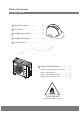
Table of Contents Installation Manual 1 Safety Precautions ..................................... 04 2 Accessories .................................................... 08 3 Installation Overview ............................... 09 4 Installation Diagram ................................ 10 5 Specifications .............................................. 11 6 Outdoor Unit Installation ......................... Outdoor Unit Installation Instructions ..... Drain Joint Installation ...................
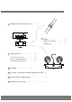
7 Refrigerant Piping Connection ............... L 15 N 8 Wiring................................................. Outdoor Unit Wiring ................... Wiring Figure ................................ 9 Air Evacuation .......................................... Evacuation Instructions ......................... Note on Adding Refrigerant ............... Safety And Leakage Check .................. 10 Test Run.......................................................
Safety Precautions 1 Read Safety Precautions Before Installation Incorrect installation due to ignoring instructions can cause serious damage or injury. The seriousness of potential damage or injuries is classified as either a WARNING or CAUTION. WARNING Failure to observe a warning may result in death. The appliance must be installed in accordance with national regulations. Failure to observe a caution may result in injury or equipment damage.
WARNING 13. An all-pole disconnection device which has at least 3mm clearances in all poles, and have a leakage current that may exceed 10mA,the residual current device (RCD) having a rated residual operating current not exceeding 30mA,and disconnection must be incorporated in the fixed wiring in accordance with the wiring rules. 14. The appliance disconnection must be incorporated with an all-pole disconnection device in the fixed wiring in accordance with the wiring rules. 15.
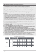
Cautions for using R32/R290 refrigerant - That mechanical connections shall be accessible for maintenance purposes. - In cases that require mechanical ventilation, ventilation openings shall be kept clear of obstruction. - When disposing of the product is used, be based on national regulations, properly processed. -The appliance shall be stored in a well-ventilated area where the room size corresponds to the room area as specified for operation.
Min. Room Area (m 2 ) Refrigerant LFL(kg/m 3 ) Type Charge Amount in kg Minimum Room Area ( m 2 ) Installation Height H0(m) 1.224 R32 0.306 1.836 2.448 3.672 4.896 6.12 7.956 0.6 29 51 116 206 321 543 1.0 10 19 42 74 116 196 1.8 3 6 13 23 36 60 2.2 2 4 9 15 24 40 Note about Fluorinated Gasses 1. This air-conditioning unit contains fluorinated greenhouse gasses. For specific information 2. 3. 4. 5.
2 Accessories The air conditioning system comes with the following accessories. Use all of the installation parts and accessories to install the air conditioner. Improper installation may result in water leakage, electrical shock and fire, or equipment failure. Name Shape Quantity Plastic expansion sheath 1 5-8 (depending on models) Self-Tapping Screw A ST3.
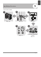
INSTALLATION ORDER 1 Install the outdoor unit (Page 10) 2 3 Connect the refrigerant pipes (Page 15) 5 L N Connect the wires (Page 18) 4 MC Perform a test run (Page 27) MC Evacuate the refrigeration system (Page 24) Page 9 Installation Overview 3 Installation Overview
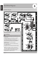
4 Installation Diagram Installation Diagram Installation Diagram 2 Air-break Switch Mounting screw ST3.9×25-C-H 1 Installation plate Clip anchor Air-break Switch Remote controller holder 1 2 Drainage Pipe 543 5 Outdoor Unit Power Cable The maximum amount of the connection cables is 5. This section is for reference only. (1) Safety Precautions Mounting screw ST3.9×25-C-H Installation plate Clip anchor CAUTION • • • • • • To prevent wall damage, use a stud finder to locate studs.
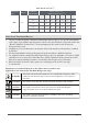
5 Specifications Power source voltage Connected units 1-5 units Stop time 3 min or more voltage fluctuation within ±10% of rated voltage voltage drop during start within ±15% of rated voltage interval unbalance within ±3% of rated voltage Table 5.2 Unit: m/ft. 1 drive 2 1 drive 3 1 drive 4 1 drive 5 Max. length for all rooms 40/131 60/197 80/262 80/262 Max. length for one indoor unit 25/82 30/98 35/115 35/115 Max.
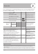
6 Outdoor Unit Installation Outdoor Unit Installation Instructions Outdoor Unit Installation Step 1: Select installation location. The outdoor unit should be installed in the location that meets the following requirements: √ Place the outdoor unit as close to the indoor unit as possible. √ Ensure that there is enough room for installation and maintenance. √ The air inlet and outlet must not be obstructed or exposed to strong wind.
Split Type Outdoor Unit (Refer to Fig 6.4, 6.5, 6.6, 6.10 and Table 6.1) Table 6.1: Length Specifications of Split Type Outdoor Unit (unit: mm/inch) Outdoor Unit Dimensions Distance A WxHxD H W W H Distance B 760x590x285 (29.9x23.2x11.2) 530 (20.85) 290 (11.4) 810x558x310 (31.9x22x12.2) 549 (21.6) 325 (12.8) 845x700x320 (33.27x27.5x12.6) 560 (22) 335 (13.2) 900x860x315 (35.4x33.85x12.4) 590 (23.2) 333 (13.1) 945x810x395 (37.2x31.9x15.55) 640 (25.2) 405 (15.95) 990x965x345 (38.
NOTE: The minimum distance between the Notes On Drilling Hole In Wall 60 cm / 23.6” above outdoor unit and walls described in the You must drill a hole in the wall for the installation guide does not apply to airtight refrigerant piping, and the signal cable that will rooms. Be sure to keep the unit unobstructed connect the indoor and outdoor units. in at least two of the three directions (M, N, P) 1. Determine the location of the wall hole (See Fig. 6.8) based on the location of the outdoor unit.
7 Refrigerant Piping Connection Safety Precautions WARNING • All field piping must be completed by a When preparing refrigerant pipes, take extra care to cut and flare them properly. This will ensure efficient operation and minimize the need for future maintenance. For R32/R290 refrigerantmodels, the pipe connection points must be placed outside of room. The connection pipes can not be reused. 1. Measure the distance between the indoor and outdoor units. 2.
Pipe Table 7.1: PIPING EXTENSION BEYOND FLARE FORM Reamer Pipe gauge Point down Tightening torque Flare dimension (A) (Unit: mm/Inch) Min. Fig. 7.2 Refrigerant Piping Connection Step 3: Flare pipe ends Proper flaring is essential to achieve an airtight seal. 1. After removing burrs from cut pipe, seal the ends with PVC tape to prevent foreign materials from entering the pipe. 2. Sheath the pipe with insulating material. 3. Place flare nuts on both ends of pipe.
NOTE: Use both a spanner and a torque wrench when connecting or disconnecting pipes to/from the unit. 7. Thread this pipeline through the wall and connect it to the outdoor unit. 8. Insulate all the piping, including the valves of the outdoor unit. 9. Open the stop valves of the outdoor unit to start the flow of the refrigerant between the indoor and outdoor unit. CAUTION Check to make sure there is no refrigerant leak after completing the installation work.
8 Wiring Safety Precautions WARNING • • • • • • Wiring • • Be sure to disconnect the power supply before working on the unit. All electrical wiring must be done according to local and national regulations. Electrical wiring must be done by a qualified technician. Improper connections may cause electrical malfunction, injury and fire. An independent circuit and single outlet must be used for this unit. DO NOT plug another appliance or charger into the same outlet.
Table 8.2: Other Regions Rated Current of Nominal Cross-Sectional Appliance (A) Area (mm²) ≤6 0.75 6 - 10 1 10 - 16 1.5 16 - 25 2.5 25- 32 4 32 - 45 6 5. Insulate unused wires with electrical tape. Keep them away from any electrical or metal parts. 6. Reinstall the cover of the electric control box. Harmonic declaration b. Using wire strippers, strip the rubber jacket from both ends of signal cable to reveal about 15cm (5.9”) of the wires inside. c.
Wiring Figure CAUTION Connect the connective cables to the terminals, as identified, with their matching numbers on the terminal block of the indoor and outdoor units. For example, in the US models shown in the following diagram, Terminal L1(A) of the outdoor unit must connect with terminal L1 on the indoor unit. NOTE: Refer to the following figures if end-users wish to perform their own wiring. Run the main power cord through the lower line-outlet of the cord clamp.
L L(A) N(A) S(A) N L(B) N(B) S(B) TO B TO A Model I POWER SUPPLY OPTIONAL Model H POWER SUPPLY OPTIONAL TO B OPTIONAL B OPTIONAL TO Y/G N S(1) S(B) N(B) L(B) L OPTIONAL A OPTIONAL TO Y/G S(2) S(A) N(A) L(A) N S(1) S(B) N(B) L(B) L OPTIONAL OPTIONAL OPTIONAL POWER SUPPLY S(2) S(A) N(A) L(A) TO A Model J NOTE: Please refer to the following figures if end-users wish to perform their own wiring.
One-four models: OPTIONAL OPTIONAL OPTIONAL OPTIONAL OPTIONAL OPTIONAL OPTIONAL OPTIONAL Model F Model E OPTIONAL OPTIONAL OPTIONAL OPTIONAL OPTIONAL OPTIONAL OPTIONAL OPTIONAL OPTIONAL POWER OPTIONAL OPTIONAL OPTIONAL OPTIONAL OPTIONAL OPTIONAL OPTIONAL SUPPLY One-five models: L(D) N(D) S(D) L(C) N(C) S(C) TO B Y/G A TO Y/G B TO Y/G A OPTIONAL OPTIONAL OPTIONAL OPTIONAL OPTIONAL OPTIONAL OPTIONAL OPTIONAL OPTIONAL OPTIONAL OPTIONAL OPTIONAL Model B Model A OPTION
OPTIONAL OPTIONAL TO D TO E N OPTIONAL TO C L OPTIONAL TO B OPTIONAL TO A TO E OPTIONAL OPTIONAL OPTIONAL OPTIONAL TO D L(C) N(C) S(C) L(D) N(D) S(D) L(E) N(E) S(E) L(A) N(A) S(A) L(B) N(B) S(B) L1 L2 OPTIONAL TO C OPTIONAL TO B OPTIONAL OPTIONAL OPTIONAL TO A Model D 1(C) 2(C) 3(C) 1(D) 2(D) 3(D) 1(E) 2(E) 3(E) 1(A) 2(A) 3(A) 1(B) 2(B) 3(B) OPTIONAL OPTIONAL OPTIONAL OPTIONAL OPTIONAL OPTIONAL OPTIONAL OPTIONAL OPTIONAL OPTIONAL Model C POWER SUPPLY Model E Model
9 Air Evacuation Safety Precautions CAUTION • Use a vacuum pump with a gauge reading lower than -0.1MPa and an air discharge capacity above 40L/min. • The outdoor unit does not need vacuuming. DO NOT open the outdoor unit’s gas and liquid stop valves. • Ensure that the Compound Meter reads -0.1MPa or below after 2 hours. If after three hours of operation and the gauge reading is still above -0.1MPa, check if there is a gas leak or water inside the pipe.
Note On Adding Refrigerant CAUTION • Refrigerant charging must be performed after wiring, vacuuming, and the leak testing. • DO NOT exceed the maximum allowable quantity of refrigerant or overcharge the system. Doing so can damage the unit or impact it’s functioning. • Charging with unsuitable substances may cause explosions or accidents. Ensure that the appropriate refrigerant is used. • Refrigerant containers must be opened slowly. Always use protective gear when charging the system.
Safety And Leakage Check Electrical safety check Perform the electrical safety check after completing installation. Cover the following areas: 1. Insulated resistance The insulated resistance must be more than 2M . 2. Grounding work After finishing grounding work, measure the grounding resistance by visual detection and using the grounding resistance tester. Make sure the grounding resistance is less than 4 . 3.
Test Run Before Test Run A test run must be performed after the entire system has been completely installed. Confirm the following points before performing the test: a) The indoor and outdoor units are properly installed. b) Piping and wiring are properly connected. c) No obstacles near the inlet and outlet of the unit that might cause poor performance or product malfunction. d) The refrigeration system does not leak. e) Drainage system is unimpeded and draining to a safe location.
Function of Automatic Wiring/Piping Correction 11 Automatic Wiring/Piping Correction Function More recent models now feature automatic correction of wiring/piping errors. Press the "check switch" on the outdoor unit PCB board for 5 seconds until the LED displays "CE”, indicatomg that this function is working, Approximately 5-10 minutes after the switch is pressed, the "CE" disappears, meaning that the wiring/piping error is corrected and all wiring/piping is properly connected.
European Disposal Guidelines 12 Users in European Countries may be required to properly dispose of this unit. This appliance contains refrigerant and other potentially hazardous materials. When disposing of this appliance, the law requires special collection and treatment. DO NOT dispose of this product as household waste or unsorted municipal waste. When disposing of this appliance, you have the following options: • Dispose of the appliance at designated municipal electronic waste collection facility.
Information Servicing (Required for the units adopt R32/R290 Refrigerant only) 13 1. Checks to the area Prior to beginning work on systems containing flammable refrigerants, safety checks are necessary to ensure that the risk of ignition is minimised. For repair to the refrigerating system, the following precautions shall be complied with prior to conducting work on the system. 2.
the charge size is in accordance with the room size within which the refrigerant containing parts are installed; the ventilation machinery and outlets are operating adequately and are not obstructed; if an indirect refrigerating circuit is being used, the secondary circuits shall be checked for the presence of refrigerant; marking to the equipment continues to be visible and legible.
11. Repair to intrinsically safe components Do not apply any permanent inductive or capacitance loads to the circuit without ensuring that this will not exceed the permissible voltage and current permitted for the equipment in use. Intrinscially safe components are the only types that can be worked on while live in the presence of a flammable atmosphere. The test apparatus shall be at the correct rating. Replace components only with parts specified by the manufacturer.
When the final OFN charge is used, the system shall be vented down to atmospheric pressure to enable work to take place. This operation is absolutely vital if brazing operations on the pipe-work are to take place. Ensure that the outlet for the vacuum pump is not closed to any ignition sources and there is ventilation available. 16.
18. Labelling Equipment shall be labelled stating that it has been de-commissioned and emptied of refrigerant. The label shall be dated and signed. Ensure that there are labels on the equipment stating the equipment contains flammable refrigerant. 19. Recovery When removing refrigerant from a system, either for service or decommissioning, it is recommended good practice that all refrigerants are removed safely.
The design and specifications are subject to change without prior notice for product improvement. Consult with the sales agency or manufacturer for details. Any updates to the manual will be uploaded to the service website, please check for the latest version.
此面无需印刷 技术 要求: 1.双胶纸(说明书)80g非E项目大度 2.尺寸:A4 3.颜色:黑白 4.注意:排版时注意页码数字都是靠外面的,以便翻阅 5.