Concealed Ducted Inside Air Handler Installation Manual Models: BM12MCD BM18MCD IMPORTANT NOTE: Read this manual carefully before installing or operating your new air conditioning unit. Make sure to save this manual for future reference. This manual only describes the outdoor unit of user’s. When using the indoor unit, refer to the user’s manual of indoor unit.
Table of Contents 1. Safety Precautions.......................................................................................................................................... 04 Owner's Manual 2. Unit Specifications and Features......................................................................................................... 06 1. Indoor unit..........................................................................................................................................................
Installation Manual 5. Accessories........................................................................................................................................................... 13 6. Installation Summary.................................................................................................................................... 14 7. Unit Parts..................................................................................................................................................
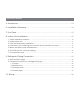
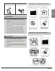
Safety Precautions 1 Read Safety Precautions Before Installation Incorrect installation due to ignoring instructions can cause serious damage or injury. The seriousness of potential damage or injuries is classified as either a WARNING or CAUTION. WARNING CAUTION This symbol indicates that ignoring instructions may cause death or serious injury. This symbol indicates that ignoring instructions may cause moderate injury to your person, or damage to your unit or other property.
WARNING 6. For all electrical work, use the specified cables. Connect cables tightly, and clamp them securely to prevent external forces from damaging the terminal. Improper electrical connections can overheat and cause fire, and may also cause shock. 7. All wiring must be properly arranged to ensure that the control board cover can close properly.
Unit Specifications 2 Unit Specifications and Features Indoor unit NOTE: The display panel shown below attaches to the control board inside the concealed ducted unit. The wired remote also must be wired through the display panel. Diagnostic codes shown on the display panel must be read at the unit. The infrared remote control is used for diagnosis only and does not communicate with the wall mounted controller.
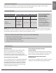
Unit Specifications Operating temperature When your air conditioner is used outside of the following temperature ranges, certain safety protection features may activate and cause the unit to disable. Inverter Split Type Room Temperature COOL mode HEAT mode DRY mode 62°F - 90°F 32°F - 86°F 50°F - 90°F 5°F - 75°F 32°F - 122°F 5°F - 122°F Outdoor Temperature (For models with low ambient cooling.
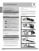
3 Care and Maintenance Care and Maintenance Cleaning Your Indoor Unit BEFORE CLEANING OR MAINTENANCE ALWAYS TURN OFF YOUR AIR CONDITIONER SYSTEM AND DISCONNECT ITS POWER SUPPLY BEFORE CLEANING OR MAINTENANCE. CAUTION Only use a soft, dry cloth to wipe the unit clean. If the unit is especially dirty, you can use a cloth soaked in warm water to wipe it clean.
If using water, the inlet side should face down and away from the water stream. If using a vacuum cleaner, the inlet side should face the vacuum. Maintenance – Long Periods of Non-Use If you plan not to use your air conditioner for an extended period of time, do the following: Care and Maintenance CAUTION • Before changing the filter or cleaning, turn off the unit and disconnect its power supply. • When removing filter, do not touch metal parts in the unit. The sharp metal edges can cut you.
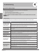
4 Troubleshooting SAFETY PRECAUTIONS Troubleshooting If any of the following conditions occurs, turn off your unit immediately! • • • • You smell a burning odor The unit emits loud or abnormal sounds A power fuse blows or the circuit breaker frequently trips Water or other objects fall into or out of the unit DO NOT ATTEMPT TO FIX THESE YOURSELF! CONTACT AN AUTHORIZED SERVICE PROVIDER IMMEDIATELY! Common Issues The following problems are not a malfunction and in most situations will not require repairs
Issue Possible Causes The outdoor unit makes noises The unit will make different sounds based on its current operating mode. Dust is emitted from either the indoor or outdoor unit The unit may accumulate dust during extended periods of non-use, which will be emitted when the unit is turned on. This can be mitigated by covering the unit during long periods of inactivity. The unit emits a bad odor The unit’s filters have become moldy and should be cleaned.
Issue Troubleshooting The unit is not working Poor Cooling Performance Poor heating performance Possible Causes Solution Power failure Wait for the power to be restored The power is turned off Turn on the power The fuse is burned out Replace the fuse Remote control batteries are dead Replace batteries The Unit’s 3-minute protection has been activated Wait three minutes after restarting the unit Timer is activated Turn timer off There’s too much or too little refrigerant in the system Che
5 Accessories The air conditioning system comes with the following accessories. Use all of the installation parts and accessories to install the air conditioner. Improper installation may result in water leakage, electrical shock and fire, or cause the equipment to fail. The items are not included with the air conditioner must be purchased separately.
6 Installation Summary 1 Installation Summary Install the indoor unit 4 2 3 Install the drainpipe 5 Install the outdoor unit 6 L N MC Connect the refrigerant pipes Page 14 Connect the wires MC Evacuate the refrigeration system Revised 5/14/2020
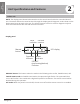
7 Unit Parts NOTE: The installation must be performed in accordance with the requirement of local and national standards. The installation may be slightly different in different areas. 2 3 1 4 1. Air outlet 2. Air inlet 3. Electric control cabinet 4. Drain pipe 5 5. Connecting pipe 6. Air inlet 7. Air outlet Unit Parts 6 6 Fig 2.1 7 NOTE ON ILLUSTRATIONS Illustrations in this manual are for explanatory purposes. The actual shape of your indoor unit may be slightly different.
8 Indoor Unit Installation Installation Instructions – Indoor Unit NOTE: Panel installation should be performed after piping and wiring have been completed. Step 1: Select installation location DO NOT install unit in the following locations: Before installing the indoor unit, you must choose an appropriate location. The following are standards that will help you choose an appropriate location for the unit.
Step 2: Hang indoor unit 1. Please refer to the following diagrams to mark the drill location of ceiling anchors. Air outlet dimensions Air inlet dimensions Air filter Descending ventilation opening and mount points Air filter Indoor Unit Installation Electric control box MODEL (Btu/h) air outlet opening size Outline dimension air return opening size Size of mounted lug A B C D E F G H I J 12K 27.6 7.9 19.9 17.7 6 21.1 7.3 23.6 29.2 14.2 18K 34.6 8.3 26.5 23.6 5.4 27.
Wooden hanging support structure Perform any necessary framing, then bolt through threaded rod to match the mount points Wood mounting Roof beam Ceiling Hanging screw bolts Cement above drop ceiling Use concrete anchors. (Blade shape insertion) 3. After you select an installation location, align the refrigerant pipes, drain pipes, as well as indoor and outdoor wires with their connection points before mounting the unit. 4. Drill 4 holes 4” deep at the ceiling hook positions in the internal ceiling.
Step 3: Duct and accessories installation 1. Install the filter at the register for maintenance access, or on the unit if direct return. Step 4: Instructions for converting from rear air return to bottom air return 1. Take off the ventilation panel and flange. Air return flange 2. Install field-supplied fiberboard supply and return plenums (if any). 3. The air inlet and air outlet duct should be far enough apart enough to a avoid air passage short-circuit. 4.
Step 5: Motor and drain pump maintenance (the rear ventilated panel is used as an example) Motor maintenance: 1. Take off the ventilated panel. 2. Take off the blower housing. 3. Take off the motor. Motor Blower housing Ventilated panel Step 6: Drill wall hole for connective piping 1. Determine the location of the wall hole based on the location of the outdoor unit. 2. Using a 2.5in core drill, drill a hole in the wall.
Step 7: Connect drain hose The drainpipe is used to drain water away from the unit. Improper installation may cause unit and property damage. CAUTION • Insulate all piping to prevent condensation, which could lead to water damage. • If the drainpipe is bent or installed incorrectly, water may leak and cause a water-level switch malfunction. • In HEAT mode, the outdoor unit will discharge water. Ensure that the drain hose is placed in an appropriate area to avoid water damage and slippage.
9 Refrigerant Piping Connection When connecting refrigerant piping, take care to keep all refrigerant lines clean and clear of debris, moisture and other contaminants. Doing so will help ensure optimal performance and longer service life. Note on Pipe Length The length of refrigerant piping will affect the performance and energy efficiency of the unit. Nominal efficiency is tested on units with a pipe length of 16.5ft. In North America, standard pipe length is 25’.
CAUTION If the outdoor unit is installed higher than the indoor unit: -It is recommended that vertical suction risers not be upsized. Proper oil return to the compressor should be maintained with suction gas velocity. If velocities drop below 1500fpm (feet per minute), oil return will be decreased. An oil trap should be installed every 20ft of vertical suction line riser.
Step 2: Remove burrs Burrs can affect the air-tight seal of refrigerant piping connection. They must be completely removed. 4. Remove PVC tape from ends of pipe when ready to perform flaring work. 1. Hold the pipe at a downward angle to prevent burrs from falling into the pipe. 5. Clamp flare form on the end of the pipe. The end of the pipe must extend beyond the edge of the flare form in accordance with the dimensions shown in the table below. 2.
Step 4: Connect pipes When connecting refrigerant pipes, be careful not to use excessive torque or to deform the piping in any way. You should first connect the low-pressure pipe, then the high-pressure pipe. Note: Use of an approved refrigerant sealant is recommended for all flare joint connections. Instructions for Connecting Piping to Indoor Unit 1. Align the center of the two pipes that you will connect. See Fig. 5.7.
10 Wiring BEFORE PERFORMING ANY ELECTRICAL WORK, READ THESE REGULATIONS 1. All wiring must comply with local and national electrical codes, regulations and must be installed by a licensed electrician. 2. All electrical connections must be made according to the Electrical Connection Diagram located on the panels of the indoor and outdoor units. 3. If there is a serious safety issue with the power supply, stop work immediately.
Indoor Unit Wiring Control box 1. Prepare the cable for connection. a. U sing wire strippers, strip the rubber jacket from both ends of the signal cable to reveal about 5.9” of the wire. b. Strip the insulation from the ends of the wires. c. Using a wire crimper, crimp the u-lugs to the ends of the wires. Wiring diagram Connective wiring diagram 2. Remove the cover of the electric control box on your indoor unit. 3. Connect the u-lugs to the terminals.
Install Outdoor Unit (see separate manual) When you have finished installing all indoor air handlers, proceed to installation of the outdoor unit. Complete installation instructions and startup procedures are given in the outdoor unit installation manual. Copies are always available at AlpineHomeAir.com by searching your unit's model number and scrolling to Documents. The design and specifications are subject to change without prior notice for product improvement. AlpineHomeAir.