
Concealed Ducted Air Handler Installation Manual


1
2
3
4
5
6
6
7
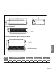
1. Air outlet
2. Air inlet
3. Electric control cabinet
4. Drain pipe
5. Connecting pipe
6. Air inlet
7. Air outlet
7
Unit Parts
NOTE ON ILLUSTRATIONS
Illustrations in this manual are for explanatory purposes. The actual shape of your indoor unit
may be slightly dierent. The actual shape shall prevail.
Fig 2.1
NOTE: The installation must be performed in accordance with the requirement of local and national
standards. The installation may be slightly dierent in dierent areas.
Unit Parts
Page 15
Revised 5/14/2020