
Multizone Outdoor Unit Installation Manual


Revised 5/14/2020
Wiring Diagrams
CAUTION
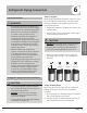
Connect the connective cables to the terminals, as identied, with their matching numbers on
the terminal block of the indoor and outdoor units. For example, in the US models shown in the
following diagram, Terminal 1(A) of the outdoor unit must connect with terminal 1 on the indoor
unit.
NOTE: Refer to the following gures if end-users wish to perform their own wiring.
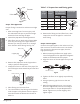
Run the main power cord through the lower line-outlet of the cord clamp.
____ This symbol indicates eld wiring.
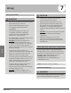
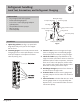
Wiring
TO A
1 2 3
TO B
1 2 3
L1 L2 1 (A)2 (A) 3 (A)1 (B)2 (B)3 (B)
POWER
Right
Ground
L1 L2 1 (A) 2 (A) 3 (A)1 (B) 2 (B) 3 (B)
TO A
1 2 3
TO B
1 2 3
POWER
Wrong
Ground
L1 L2 1 (A) 2 (A) 3 (A)1 (B) 2 (B) 3 (B)
TO A
1 2 3
TO B
POWER
1 2 3
Ground
Wrong
Page 16
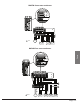
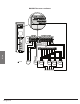
BM18M two zone condenser:
TO A
1 2 3
D
D
C
C
B
B
A
A
L1 L2 1 (A)2 (A) 3 (A)1 (B)2 (B)3 (B)
L1 L2 1 (A)2 (A) 3 (A)1 (B)2 (B)3 (B)
TO B
1 2 3
POWER
L1 L2 1 (A)2 (A) 3 (A)1 (B)2 (B)3 (B)
Ground