
Multizone Outdoor Unit Installation Manual


Revised 5/14/2020
NOTE: Gauge shown in Table 8.1 is for 50' run
or less. For longer runs, consult an electrician.
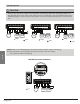
NOTE: While connecting the wires, please
strictly follow the wiring diagram (found inside
the electrical box cover).
Follow these instructions to prevent distortion
when the compressor starts:
• The unit must be connected to the main out-
let. Normally, the power supply must have a
low output impedance of 32 ohms.
• No other equipment should be connected to
the same power circuit.
• The unit’s power information can be found on
the rating sticker on the product.
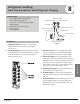
1. Prepare the cable for connection
a. You must rst choose the right gauge wire
before preparing it for connection.
b. Refer to the table above for 50 foot and
under. For over 50 foot runs, consult an
electrician.
c. Using wire strippers, strip the rubber jack-
et from both ends of signal cable to reveal
about 6” of wire.
d. Strip the insulation from the ends of the
wires.
e. Using a wire crimper, crimp u-lugs on the
ends of the wires.
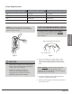
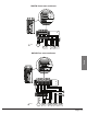
2. Remove the electric cover of the outdoor
unit. If there is no cover on the outdoor
unit, disassemble the bolts from the main-
tenance board and remove the protection
board. (See Fig. 8.1)
Wiring
Cover
Screw
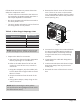
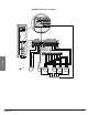
3. Connect the u-lugs to the terminals Match
the wire colors/labels with the labels on
the terminal block, and rmly screw the
u-lug of each wire to its corresponding
terminal.
4. Clamp down the cable with designated
cable clamp.
5. Insulate unused wires with electrical tape.
Keep them away from any electrical or
metal parts.
6. Reinstall the cover of the electric control
box.
Page 15
Table 8.1: Wire Gauge/ Amperage chart
Rated Current of
Appliance (A)
Wire Gauge
13 - 18 14
18 - 25 12
25 - 30 10
30 - 50 8
Fig 8.1