
Multizone Wall Mounted Air Handler Installation Manual
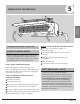

Indoor Unit
Installation
Page 13
Revised 5/14/2020
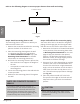
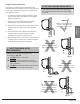
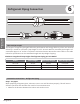
Correct orientation of Mounting Plate
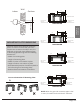
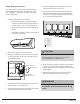
MOUNTING PLATE DIMENSIONS
Dierent models have dierent mounting
plates. In order to ensure that you have
ample room to mount the indoor unit, the
diagrams to the right show dierent types
of mounting plates along with the following
dimensions:
• Width of mounting plate
• Height of mounting plate
• Width of indoor unit relative to plate
• Height of indoor unit relative to plate
• Recommended position of wall hole (both to
the left and right of mounting plate)
• Relative distances between screw holes
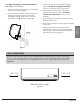
Fig 3.2
Wall
Indoor
Outdoor
1/4" to 1/2"
BM09M22WM
4”
7.05in”
5.35”
1.45”
11.4”
1.95”
Right rear wall
hole 2.5”
Left rear wall
hole 2.5”
Indoor unit outline
28.45”
1.95”
13.7”
BM12M22WM
7.55”
9.15”
16.8”
5.05”
1.7”
11.7”
Left rear wall
hole 2.5”
Right rear wall
hole 2.5”
Indoor unit outlin
e
31.6”
1.7”
1.7”
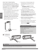
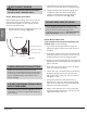
BM18M21WM
5.65”
2.3”
12.55”
2.25”
1.55”
Right rear wall
hole 2.5”
Left rear wall
hole 2.5”
38”
15.45”
1.35”
Indoor unit outline
20.37”
BM24M21WM
8.6”
21.77”
11.8”
13.2”
Left rear wall
hole2.5”
Right rear wall
hole 2.5”
42.5”
2.1”
1.85”
3”
2.1”
1.85”
5.85”
5.95”
6.85”
Indoor unit outline
NOTE: When the gas side connective pipe is 5/8"
or more, the wall hole should be 3.5 "diameter.