Owner's Manual Original Instructions Split Air Conditioner Thank you for choosing our product. Please read this Owner’s Manual carefully before operation and retain it for future reference.
Content Safety precautions ................................................................. 01 Parts name .......................................................................... 05 Operation and introduction of remote contr oller ........................ 06 Clean and maintenance ......................................................... 13 Checked items before maintenance ........................................ . 14 Installation notice ...................................................................
Explanation of Symbols WARNING This symbol indicates the possibility of death or serious injury. CAUTION This symbol indicates the possibility of injury or damage to property. NOTICE Indicates important but not hazard-related information, used to indicate risk of property damage. Exception Clauses Manufacturer will bear no responsibilities when personal injury or property loss is caused by the following reasons. 1.Damage the product due to improper use or misuse of the product; 2.
Fcc Warning WARNING: Changes or modifications to this unit not expressly approved by the party responsible for compliance could void the user’s authority to operate the equipment. Fcc Statement This device complies with Part 15 of the FCC Rules.Operation is subject to the following two conditions : (1) this device may not cause harmful interference, and (2) this device must accept any interference received,including interference that may cause undesired operation.
Ic Statement This equipment complies with FCC’s and IC’s RF radiation exposure limits set forth for an uncontrolled environment. The antenna(s) used for this transmitter must be installed and operated to provide a separation distance of at least 20 cm from all persons and must not be collocated or operating in conjunction with any other antenna or transmitter. Installers must ensure that 20cm separation distance will be maintained between the device (excluding its handset) and users.
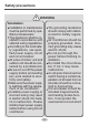
Safety precautions WARNING Installation Installation or maintenance must be performed by qualified professionals. The appliance shall be installed in accordance with national wiring regulations. According to the local safety regulations, use qualified power supply circuit and circuit breaker. All wires of indoor unit and outdoor unit should be connected by a professional. Be sure to cut off the power supply before proceeding any work related to electricity and safety.
Safety precautions CAUTION Installation Instructions for installation and use of this product are provided by the manufacturer. Select a location which is out of reach for children and far away from animals or plants. If it is unavoidable, please add the fence for safety purpose. The indoor unit should be installed close to the wall. Don't use unqualified power cord. If the length of power connection wire is insufficient, please contact the supplier for a new one.
Safety precautions WARNING Operation and Maintenance This appliance can be used by children aged from 8 years and above and persons with reduced physical, sensory or mental capabilities or lack of experience and knowledge if they have been given supervision or instruction concerning use of the appliance in a safe way and understand the hazards involved. Children shall not play with the appliance. Cleaning and user maintenance shall not be made by children without supervision.
Safety precautions CAUTION Operation and Maintenance Do not spill water on the remote controller, otherwise the remote controller may be broken. Do not use fire or hair dryer to dry the filter to avoid deformation or fire hazard. Do not block air outlet or air inlet. It may cause malfunction. Do not step on top panel of outdoor unit, or put heavy objects. It may cause damage or personal injury.
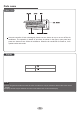
Parts name Indoor Unit If remote controller is lost or damaged, please use aux. button to turn on or turn off the air conditioner. The operation in details is as below: As shown in the figure, open panel and press aux. button to turn off the air conditioner. When the air conditioner is turned on, it will operate under auto mode. Display Temp. indicator Power indicator NOTE ● This is the general introduction and the color of indicator is only for reference. Please refer to the actual display.
Operation and introduction of remote controller Introduction for icons on display screen Operation mode Buttons on remote controller FAN - FAN TURBO + MODE MODE ON/OFF (before opening cover) CLOCK TIMER OFF TIMER ON TEMP ON/OFF I FEEL LIGHT WiFi QUIET I feel Set fan speed Turbo mode Send signal Auto mode Cool mode Dry mode Fan mode Heat mode Sleep mode 8°C heating function Health mode Scavenging function WiFi function Quiet X-FAN function Set temp. Temp.
Introduction for buttons on remote controller ● This function indicates that moisture on evaporator of indoor unit will be blowed after the unit is stopped to avoid mould. NOTE ● This is a general use remote controller. It could be used for the air conditioner with multifunction. For the functions which the model doesn't have, if press the corresponding button on the remote controller, the unit will keep the original running status.
button TIMER OFF TIMER ON button ● Timer On setting: Signal "ON" will blink and Press this button to set left & right swing angle cycling as below: display, signal will conceal, the numerical section will become the timer on setting status. During 5 seconds blink, by pressing + or - button to adjust the time value of numerical section, every press of that button, the value will be increased or decreased 1 minute.
NOTE NOTE ● This function is only available for some models. ● Outdoor temperature display is not available for some models. At that time, indoor unit receives " signal, while it displays indoor set temperature. " QUIET Press this button, the quiet status is under the auto quiet mode (display " " and "Auto" signal) and quiet mode (display " " signal) and quiet off (there is no signal of " " displayed), after powered on, the quiet off is defaulted. Under the quiet mode (Display " " signal).
(4) When setting the initial temperature 30°C, under this temperature setting, after 7hours, the temperature will be decreased 1°C, after that the unit will keep on running under this temperature; In heat mode: (1) Under the initial presetting temperature 16°C, it will run under this setting temperature all along. (2) Under the initial presetting temperature 17°C -20°C, after Sleep function started up, the temperature will decrease 1°C in every hour, after 1°C decreased, this temperature will be maintained.
3 speed or quiet mode according to the comparison between indoor ambient temperature and set temperature. 3. Under dry, fan mode: indoor fan operates at quiet mode. 4. Under auto mode: the indoor fan operates at the auto quiet mode according to actual cooling, heating or fan mode. About swing left and right 1.
Replacement of batteries in remote controller battery reinstall remove Cover of battery box 1. Press the back side of remote controller marked with " ", as shown in the fig, and then push out the cover of battery box along the arrow direction. 2. Replace two 7# (AAA 1.5V) dry batteries, and make sure the position of "+" polar and "-" polar are correct. 3. Reinstall the cover of battery box. NOTICE ● During operation, point the remote control signal sender at the receiving window on indoor unit.
Clean and maintenance WARNING ■ The filter should be cleaned every three months. If there is much dust in the operation environment, clean frequency can be increased. ■ After removing the filter, do not touch fins to avoid injury. ■ Do not use fire or hair dryer to dry the filter to avoid deformation or fire hazard. WARNING ■ Turn off the air conditioner and disconnect the power before cleaning the air conditioner to avoid electric shock.
Checked items before maintenance Phenomenon General phenomenon analysis Please check below items before asking for maintenance. If the malfunction still can’t be eliminated, please contact local dealer or qualified professionals. Phenomenon Check items Whether it's interfered severely (such as static electricity, stable voltage?) No air emitted from indoor unit Whether there are obstacles? Pull out the plug. Reinsert the plug after about 3min, and then turn on the unit again. Remove obstacles.
Installation notice WARNING sure that the unit is running in cooling mode. Then, fully close the valve at high pressure side (liquid valve). About 30-40 seconds later, fully close the valve at low pressure side (gas valve), immediately stop the unit and disconnect power. Please note that the time for refrigerant recovery should not exceed 1 minute. If refrigerant recovery takes too much time, air may be sucked in and cause pressure rise or compressor rupture, resulting in injury.
Requirements for electric connection Selection of installation location Basic requirement 7.If the supply cord is damaged, it must be replaced by the manufacturer, its service agent or similarly qualified persons in order to avoid a hazard . 8.The temperature of refrigerant circuit will be high, please keep the interconnection cable away from the copper tube. 9.The appliance shall be installed in accordance with national wiring regulations.
Installation of indoor unit NOTE Step 1: Choose installation location outdoor Φ55 Φ70 5-10 Recommend the installation location to the client and then confirm it with the client. Step 2: Step 4: Install wall-mounting frame Outlet pipe 1.Hang the wall-mounting frame on the wall; adjust it in horizontal position with the level meter and then point out the screw fixing holes on the wall. 1. The pipe can be led out in the direction of right, rear right, left or rear left. 2.
drain hose Hex nut diameter Tightening torque (N m) 15~20 30~40 45~55 insulating pipe NOTE 70~75 Add insulating pipe in the indoor drain hose in order 4 Wrap the indoor pipe and joint of connection pipe with insulating pipe, and then wrap it with tape Step 7: Connect wire of indoor unit NOTICE All wires of indoor unit and outdoor unit should be If the length of power connection wire is insufficient, insulating pipe For the air conditioner with plug, the plug should be For the air conditioner witho
drain hose connection pipe 3. Remove the wire clip; connect the power connection wire to the wiring terminal according to the color; tighten the screw and then fix the power connection wire with wire clip. band indoor power cord N(1) 2 3. Bind them evenly. 4. The liquid pipe and gas pipe should be bound separately at the end. 3 white black red green (blue) (brown) (yellowgreen) NOTICE ● The power cord and control wire can't be crossed or winding. ● The drain hose should be bound at the bottom.
Test and operation Check after installation ● Check according to the following requirement after finishing installation. Items to be checked Has the unit been installed firmly? Have you done the refrigerant leakage test? Possible malfunction The unit may drop, shake or emit noise. It may cause insufficient cooling(heating) capacity. Is heat insulation of pipe- It may cause condensation and water dripping. line sufficient? Is water drained well? It may cause condensation and water dripping.
Configuration of connection pipe 48000Btu/h (14064W) 30 350 120 120 50 20 250 350 30 _ 42000Btu/h (12306W) 7/8'' 30 250 36000Btu/h (10548W) _ 30 3/4'' 28000Btu/h (8204W) 60 25 1'' or 1 1/4'' 24000Btu/h (7032W) 5/8'' 25 30 18000Btu/h (5274W) 3/4'' or 7/8'' 20 1/2'' 12000Btu/h (3516W) 15 15 5/8'' or 3/4'' 9000Btu/h (2637W) 1/4'' or 3/8'' 15 15 7000Btu/h (2051W) 3/8'' or 1/2'' 15 1/4'' 5000Btu/h (1465W) Cooling only(g/m) Max.
B: Remove the burrs smooth surface ● Remove the burrs with shaper and prevent the burrs from getting into the pipe. improper expanding pipe shaper downwards the length is equal leaning damaged crack surface uneven thickness Working temperature range C: Put on suitable insulating pipe Maximum cooling D: Put on the union nut Maximum heating ● Remove the union nut on the indoor connection pipe and outdoor valve; union pipe install the union nut on the pipe.
66129935292