Ductless Mini Split Installation & Owner’s Manual Document Version: 11/2016
Blueridge Owners Manual 1 Table of Contents 1. Table of contents 2 2. Cover Sheet 4 3. Applicable Blueridge Models 5 4. Important Safety Instructions and Notices 6 5. Installation Tools 8 6. Unit Installation Clearances 9 7. Installation of the Indoor Air Handler 10 8. Installation of a Single Zone Outdoor Unit 18 9. Installation of a Multizone Outdoor Unit 23 10. Leakage Detection 28 11. Vacuum 28 12. Remote Controls 32 12.1 15 SEER Models 32 12.
Blueridge Owners Manual 3 Document Version: 11/2016 Copyright 2016 Alpine Home Air Products
Blueridge Owners Manual 2 For Your Records Outdoor Model # Outdoor Serial # This can be found on the outdoor unit or on the sticker on the side of the box Zone 1 Indoor Air Handler Model # Indoor Air Handler Serial # This can be found on the indoor air handler or on the sticker on the side of the box If applicable ...
Blueridge Owners Manual 3 Applicable Blueridge Models This document applies to the following Blueridge Ductless Heat Pump featuring High Efficiency Inverter Technology models: BMKH18M-NDG3 BMKH30-NDG3 All Blueridge Multizone Heat Pump Systems 5 Applicable Blueridge Models Document Version: 11/2016 Copyright 2016 Alpine Home Air Products
Blueridge Owners Manual 4 • Important Safety instructions and Notices While 90% of the mechanical work can be done by a mechanically inclined individual, the final 10% consisting of electrical wiring, vacuuming, leak testing, and starting the system should be done by a qualfied professional. • Due to the potential for injury, any troubleshooting or diagnosing should be done by a qualified professional. This includes troubleshooting with refrigerant, electricity, or unit operation.
Blueridge Owners Manual • If any malfunction of the Heat Pump System occurs, take note of any error code or flashing lights that may be displayed on the indoor unit, turn the system off and disconnect the power immediately. Only a qualified person should power on and troubleshoot the system. NOTE Your actual heat pump system and related devices may differ from the images shown in this manual. This appliance is not intended for use other than stated in this manual.
Blueridge Owners Manual 5 Installation Tools Standard Wrench Adjustable/Crescent Wrench Torque Wrench Hex Keys or Allen Wrenches Drill & Drill Bits Hole Saw Pipe Cutter Screw Drivers (Phillips & Flat blade) Menifold and Gauges Level R410A Flaring Tool Clamp on Amp Meter Vacuum Pump Safety Glasses Work Gloves Refrigerant Scale Micron Gauge 8 Installation Tools Document Version: 11/2016 Copyright 2016 Alpine Home Air Products
Blueridge Owners Manual 6 Unit Installation Clearances Installation Dimension Diagram At least 6” Space to the ceiling At least 6“ At least 6” 6” Between unit and wall Between unit and wall 6” 6” Indoor Unit Lineset Bundle At least 6 ft Lineset, connecting wires, and drain tubing leave the rear of the indoor unit and go through a hole drilled on an outer wall, to connect to the outdoor unit 6.
Blueridge Owners Manual 7 Installation of the Indoor Air Handler Mechanical Installation of the Air Handler 1 Choose a Location Blueridge Ductless minisplits are extremely versatile for the fact that they can be retrofitted in a limitless number of applications. There are a few restrictions to keep in mind when it comes to selecting the location of the indoor air handler.
Blueridge Owners Manual 2 Mount the Air Handler’s Bracket • Hold the air handler’s wall mounting frame on the wall. Use a level to ensure the mounting frame is horizontally level, and use a pencil to mark the desired screw holes. • Drill the marked holes to create a pilot hole. • Affix the wall mounting frame to the wall using appropriately sized self tapping screws w/anchors. Check to ensure the wall mounting frame is firmly affixed to the wall by pulling on it.
Blueridge Owners Manual 3 Drill the piping hole in the wall Inside Outside Wall Wall Sleeve 10-15o Hole Size Seal Hole Piping Img 2 | Side view of hole drilled in wall Img xx Wall Hole drilling diagram • Choose the location of the piping hole based on the desired left or right side outlet from the air handler. This hole will need to be large enough to accommodate the copper lines, multiconductor wire, and drain tube. Most customers purchase and install a wall sleeve ranging from 2.
Blueridge Owners Manual 4 Piping Orientation Left Side View Remove Panel Indoor Air Handler Wall Img 3 | View of side panel locations wiring can be run through • The pipes can be led in four different directions. They can be orientated from the right of the unit, left of the unit, right rear of the unit (straight out the piping hole in Step Three), and the left rear of the unit (straight out the piping hole in Step Three).
Blueridge Owners Manual 5 Connecting the Piping • Use caution when prepping the air handler to connect the copper line set. The air handler will be be pressurized with dry nitrogen, which keeps the unit free of moisture and indicates that the air handler doesn’t have refrigerant leaks. When removing the plugs, the nitrogen will release. If the nitrogen is not present in the air handler at time of installation, stop installation and call Alpine’s technical support.
Blueridge Owners Manual 6 Draining • The drain hose can be connected to either side of the air handler. There is a plug on one end and a drain hose on the other. To properly drain the indoor air handler, connect the drain tube to the same side as the copper lines. Insert the drain plug in the other side. • Insulate the Drain Tubing. 7 Connect the multiconductor wire • Open the front panel of the indoor air handler, remove the screw on the wiring cover, and remove the cover.
Blueridge Owners Manual Back of Air Handler Wire Img 4a |Pull wire through the back of the unit before connecting Front of Air Handler (Panel Open) N(1) Black 2 White 3 Red Green L1 Black L2 Red N (1) 2 3 B W R G Img 4b | Connecting Wires on the indoor unit NOTE • All wires of both the indoor air handler and outdoor heat pump should be connected by a professional. • Do not extend high or low voltage wiring during installation. Avoid wire extension by using the proper length of wire.
Blueridge Owners Manual 8 Band the copper lines, wire, and drain hose • Bind the copper lines, the multiconductor wire, and drain hose up with a band as seen in Img 5. • Take into consideration that the drain tubing will not run the entire distance as the copper lines, so allow the drain tubing to escape this binding where the contractor sees fit.
Blueridge Owners Manual 8 Installation of a Single Zone Outdoor Unit Mechanical Installation of the Outdoor Unit 1 Select a Location • Select the outdoor unit’s installation location based on the home’s structure, local codes, and convenience of installation. (See Page 8) • Ideally, these outdoor units are installed in a location that is well ventilated and dry, in which the outdoor unit will not be exposed directly to sunlight and wind.
Blueridge Owners Manual 3 Mount the Outdoor Unit • Mount the outdoor unit to a concrete pad, plastic pad, or wall bracket of your choice, using the foot holes and bolts. Foot Holes Foot Holes Img 7 | Footholes located at the botton of the outdoor unit 4 Connect the Copper Lines • Remove the screw on the right handle of the outdoor unit. • Slide the cover down to take the panel off and expose the valves. • Remove the screw cap of the valves.
Blueridge Owners Manual • Hex Nut Diameter (in) Tightening Torque (ft-lbs) 1/4 10-13 3/8 25-30 1/2 36-45 5/8 50-60 If the lines are not already insulated, wrap them with insulation and tape the insulation in place. 5 Wiring the Air Handlers to the outdoor unit • Remove the wire clip on the outdoor unit. • Connect the multi conductor wire that is run from the indoor air handler to the associating terminals on the outdoor unit.
Blueridge Owners Manual N(1) Black 2 White 3 Red Green L1 Black L2 Red Indoor Air Handler Unit Electrical Disconnect Outdoor Unit Line Set Connection Electrical Whip Indoor Unit Connection N(1) B Electrical Disconnect Connection 3 2 W R L1 L2 B R G G Img 8 | How to wire the outdoor unit for Single Zone Units Installation of a Single Zone Outdoor Unit Document Version: 11/2016 Copyright 2016 Alpine Home Air Products 21
Blueridge Owners Manual 6 Copper Line Presentation • The copper lines should be run along the wall and as hidden as possible. Minimum semi diameter of bending the pipe is 4 inches. Indoor Unit • If the outdoor unit is higher than the wall piping hole, a U-Shaped curve should be bent into the copper lines before the pipe goes into the wall. This Wall Outdoor Unit prevents moisture from running down the lines and into the conditioned space.
Blueridge Owners Manual 9 Installation of a Multizone Outdoor Unit Mechanical Installation of Multizone Outdoor Unit 1 Choose a Location • Select the outdoor unit’s installation location based on the home’s structure, local codes, and convenience of installation. • Ideally, these outdoor units are installed in a location that is well ventilated and dry, in which the outdoor unit will not be exposed directly to sunlight and wind.
Blueridge Owners Manual 3 Mount the Outdoor Unit • Mount the outdoor unit to a concrete pad, plastic pad, or wall bracket your choice, using the foot holes and bolts. Foot Holes Foot Holes Img 11 | Footholes located at the botton of the outdoor unit 4 Connect the Copper Lines • Remove the screw on the right handle of the outdoor unit. • Slide the cover down to take the panel off and expose the valves. • Remove the screw cap of the valves.
Blueridge Owners Manual • Hex Nut Diameter (in) Tightening Torque (ft-lbs) 1/4 10-13 3/8 25-30 1/2 36-45 5/8 50-60 If the lines are not already insulated, wrap them with insulation and tape the insulation in place. 5 Wiring the Air Handlers to the outdoor unit • Remove the wire clip on the outdoor unit. • Connect the multi conductor wire that is run from the indoor air handler to the associating terminals on the outdoor unit.
Blueridge Owners Manual N(1) Black 2 White 3 Red Indoor Air Handler Unit Electrical Disconnect Outdoor Unit Green L1 Black L2 Red Line Set Connection Zone 1 G 3 2 N(1) B W Zone 2 R N(1) B W Zone 3 3 2 Electrical Whip N(1) R B 3 2 W Zone 4 R N(1) B 3 2 W R G Indoor Unit Connection G G L1 L2 B R G Img 12 | How to wire the outdoor unit for Multi Zone Units 26 Installation of a Multi Zone Outdoor Unit Document Version: 11/2016 Copyright 2016 Alpine Home Air Pro
Blueridge Owners Manual 6 Copper Line Presentation • The copper lines should be run along the wall and as hidden as possible. Minimum semi diameter of bending the pipe is 4 inches. • If the outdoor unit is higher than the wall piping hole, a U-Shaped curve should be bent into the copper lines before the pipe goes into the wall. This prevents moisture from running down the lines and into the conditioned space.
Blueridge Owners Manual 10 • Leak Detection The refrigerant system must be completely sealed in order for the Blueridge Ductless System to perform optimally and prevent damage to the equipment. • If a refrigerant detector is not available, soap and water can be used. • The lineset(s) should be pressurized using dry nitrogen, 100-200 psig. Then using a soap bubble solution, spray down all flare joints, and watch for bubbles to appear.
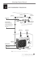
Blueridge Owners Manual Indoor Unit (Inside House, attached to other side of wall) Wall Outdoor Unit Gauges Drain Pipe Copper Line Sets (attached) Service Valve Vacuum Pump Img 13 | Vacuuming the lines Vacuuming Document Version: 11/2016 Copyright 2016 Alpine Home Air Products 29
Blueridge Owners Manual Single Zone (cont) • After the copper lines have been connected, and the pressure test is complete, you may connect your vacuum pump, manifold gauges, micron gauges and evacuate the lines. • Once it is confirmed that the joints have a proper connection, pull a vacuum down to 500 microns. • After the vacuum is complete, close manifold gauge valve(s), and open both the service valves fully, release the refrigerant into the system, and start the system.
Blueridge Owners Manual Multizone: • Connect each zone’s copper lines one at a time. After connecting the first set of copper lines, and the pressure test is complete, connect your manifold gauges, micron gauge, and vacuum pump and evacuate the lineset. • Once it is confirmed that the joints have a proper connection, pull a vacuum down to 500 microns.
Blueridge Owners Manual 12 Remote Control 12.
Blueridge Owners Manual NOTE • When the power is connected (stand by condition), you can operate the air conditioner using the remote control. • When the unit is on, each time you press a button on the remote controller, the sending signal icon “ “ on the display of remote control will blink once. If the air conditioner beeps, that means the signal has been sent.
Blueridge Owners Manual • When selecting dry mode, the air handler will run in air conditioning, but with a low fan sped to remove excess humidity. In dry mode, the fan speed cannot be adjusted. • When selecting fan mode, the air handler will only operate the fan. Press the FAN button to adjust the fan speed. • When selecting heat mode, the air handler provides heat. Press + or button to adjust the set temperature. Press the FAN button to adjust the fan speed.
Blueridge Owners Manual AUTO NOTE • Under Auto speed, air conditioner will select proper fan speed automatically according to ambient temperature. • Fan speed cannot be adjusted under Dry Mod. 5 SWING Button Press this button to turn on up & down air swing. 6 SLEEP Button Under the Cool, Heat, and Dry modes, press the sleep button to engage sleep mode. Press this button to cancel Sleep mode. Under the Fan and Auto modes this function is unavailable.
Blueridge Owners Manual 7 TIMER Button • When the unit is on, press the timer button to set Timer Off. T-OFF and H icon will be blinking. Within 5s, press the + or - button to adjust the time for Timer Off. Pressing + or - button once will increase or decrease the time by 0.5h. Hold the + or - button for 2s and the time will change quickly. Release the button after your required set time is reached. Then press TIMER button to confirm the set time. T-OFF and H icon will stop blinking.
Blueridge Owners Manual Function for combination buttons 1 Child lock function Press the “+” and “-” buttons simultaneously to turn on or turn off the child lock function. When the child lock function is started up, LOCK indicator on remote controller is ON. If any buttons are pressed while the lock indicator is ON, the remote controller will not send the signal. 2 Temperature display switchover function Pressing “-” and “MODE” buttons simultaneously will change the remote back and forth from oC and oF.
Blueridge Owners Manual Replacement of batteries in remote control 1. Press the back side of remote controller on the spot marked ” Battery “, and pull off the battery box. 2. Replace two No.7 (AAA 1.5V) dry Reinstall batteries and make sure the posi- Remove tions or + and - polar are correct. Cover of Battery Box 3. Reinstall the cover of the battery Img 15 | Back of 15 Seer Unit Remote box. NOTE • During Operation, point the remote controller signal sender at the indoor air handler.
Blueridge Owners Manual 12.
Blueridge Owners Manual NOTE • When the power is connected (stand by condition), you can operate the air conditioner using the remote control. • When the unit is on, each time you press a button on the remote controller, the sending signal icon “ “ on the display of remote control will blink once. If the air conditioner beeps, that means the signal has been sent.
Blueridge Owners Manual • After selecting cool mode, the air handler will operate under cool mode. Cool indicator “ “ on indoor unit is ON. Press “+” or “-” button to adjust the set temperature. Press the “FAN” button to adjust the fan speed. Press “ “ button to adjust the fan blowing angle. • When selecting dry mode, the air handler will operate in air conditioning, but with a low fan speed to remove excessive humidity. Dry indicator “ “ on indoor unit is ON.
Blueridge Owners Manual 3 +/- Button • Press the “+” or “-” buttons once to increase or decrease the set temperature 1 oF. Hold the “+” or “-” button on the remote controller to change the temperature quickly. Release the button after your desired temperature is reached. (Temperature cannot be adjusted under auto mode). • When setting the TIMER ON, TIMER OFF or CLOCK, press “+” or “-” button to adjust time. (Refer to CLOCK, TIMER ON, TIMER OFF buttons).
Blueridge Owners Manual • When selecting “ “, the air handler’s horizontal louver will automatically swing up & down at maximum angle. • When selecting “ , , , , “, the air handler’s louver will stop at the fixed position. • When selecting “ , , “, the air handler’s louver will send air at the fixed angle. • Hold the “ “ button for 2s to set your desired swing angle. Release the button once you are satisfied with the louver’s position. NOTE “ , , “ may not be available.
Blueridge Owners Manual 7 TIMER ON/ TIMER OFF Button TIMER ON - Button can set the timer for timed operation. After pressing this button, “ “ icon disappears and the word “ON” on the remote controller blinks. Press the “+” or “-” button to adjust the TIMER ON setting. After each pressing of the “+” or “-” button, the TIMER ON setting will increase or decrease 1min. Hold the “+” or “-” button for 2s and the time will change quickly until reaching your desired time. Press the “TIMER ON” to confirm it.
Blueridge Owners Manual 8 X-FAN Button Press this button under cool and dry mode to start up x-fan function, and the “ “ icon will display on the remote controller. Press the button again to cancel x-fan function, and the “ “ will disappear. NOTE • When the x-fan function is on, if the air conditioner is turned off, the indoor fan will still operate on low speed for a few minutes to blow the residual water inside the air duct.
Blueridge Owners Manual NOTE • The outdoor temperature display is not available for some models. If the indoor unit receives “ “ signal, it will display the indoor set temperature. • The default display will show the set temperature when the unit is pressed on. • When selecting the indoor or outdoor’s ambient temperature, the display will show the selected valve for 3 seconds and return back to the set temperature.
Blueridge Owners Manual In Cool or Dry modes: The unit will run at current room setpoint for 1 hour. After 1 hour, the setpoint will increase by 2 oF. After 2 hours, the setpoint will increase by 4 oF and maintain this setpoint until Sleep Mode is cancelled. In Heat Mode: The unit will run at current room setpoint for 1 hour. After 1 hour, the setpoint will decrease by 2 oF. After 2 hours, the setpoint will decrease by 4 oF and maintain this setpoint until Sleep Mode is cancelled.
Blueridge Owners Manual Operation Guide 1. After connecting the power, press the “ON/OFF” button on remote controller to power up the ductless mini split. 2. Pressing the “MODE” button will select your desired mode: AUTO, COOL, DRY, FAN, HEAT. 3. Press the “+” or “-” buttons to set your desired temperature. (The temperature cannot be adjusted when the unit is in auto mode). 4. Press the “FAN” button to set your desired fan speed: auto, low, medium, and high speed. 5.
Blueridge Owners Manual Replacement of batteries in remote control Signal Sender 1. Battery Press the back side of remote controller on the spot marked ” “, and then pull the cover off of the battery box. 2. Reinstall Remove Replace two No.7 (AAA 1.5V) dry batteries and make sure the + and - positons are correct. 3.
Blueridge Owners Manual 12.3 Emergency Operation If the remote control is lost or damaged, the heat pump can be turned on and off by using the AUX button. The AUX button is located underneath the front panel on the right hand side. When the AUX button is pressed, the system will run in auto mode. In auto mode, the system will run off of optimal conditions based on the ambient temperature, and the temperature cannot manually be adjusted. The temperature settings are 77 oF for cooling and 68 oF for heating.
Blueridge Owners Manual 13 Cleaning and Maintenance 1 Open Panel Pull up on the front left and right of the air handler’s cover as shown in figure 1 Figure 1 2 Remove Filter Remove the filter as indicated in figure 2. There are two filters, one on each side. Press up on the middle tab on each filter to take it out. Figure 2 3 Clean Filter • Use dust catcher or water to clean. • When the filter is very dirty, the water (below 113 oF) to clean it, and then put it in a shady and cool place to dry.
Blueridge Owners Manual NOTE • The indoor air handler’s filter should be cleaned every three months, but may require cleaning more often based on the conditions of the room. It is not harmful to increase the cleaning frequency. • Use caution after the filter has been removed. The fins of the evaporator coil will be exposed and are very sharp. Do not touch the fins, as touching the fins can cause injury as well as a decrease in the unit’s performance.
Blueridge Owners Manual 14 Operating Ranges Operating ranges of Blueridge 15 SEER Single Zone Ductless Minisplits Indoor Side DB/WB (F) Outdoor Side DB/WB (F) Maximum Cooling 89.6 / 73.4 109.4 / 78.8 Maximum Heating 80.6 75.2 / 64.4 The operating temperature range (Outdoor Temperature) for cooling is 64.4 F ~109.4 F; for heating it is 19.4 F ~ 75 F.
Blueridge Owners Manual 5 15 Copper Line Length Guidelines Single Zone - 15, 16, 18, 20, and 22 SEER Blueridge Minisplits Unit Capacity (BTU’s/Hour) Min Line Set Length Max Line set Length Max Height Difference 9,000 10 Feet 50 Feet 15 Feet 12,000 10 Feet 66 Feet 30 Feet 18,000 10 Feet 82 Feet 30 Feet 24,000 10 Feet 82 Feet 30 Feet 30,000 10 Feet 100 Feet 30 Feet 36,000 10 Feet 100 Feet 60 Feet Multi Zone - Since several different zones share the refrigerant of a multizone, t
Blueridge Owners Manual 5 16 Copper Line Flaring NOTE Improper pipe flaring is the main cause of refrigerant leakage. Pipe Pipe Cutter Please flare the pipe according to the following steps Pipe 1 Cut the Pipe • Pipe Cutter Confirm the pipe length according to the distance of indoor unit and outdoor unit.
Blueridge Owners Manual 5 Flare the port Flare the port with a flaring tool. “A” (Heightof pipe above expander base) Expander Note “A” is different according to the Expander diameter, refer to the table below A (mm) Outer Diameter (mm) Max Min 6-6.35 (1/4”) 1.3 0.7 9.52 (3/8”) 1.6 1.0 12-12.7 (1/2”) 1.8 1.0 15.8-16(5/8”) 2.4 2.2 Pipe 6 Inspect Check the quality of the flaring port. If there is any blemish, flare the port again according to the steps above.
Blueridge Owners Manual 5 17 Installing Optional Air Filters • All Blueridge indoor air handlers come with air filters installed • Optional air filters are available To Install the Filter: • Lift the front panel and remove the air filter • Attach the optional filter into the air filter • Reinstall the air filter and close the panel 5 18 Start Up Complete a full system check prior to starting the system • Make sure the drain hose slopes downward along entire length.
Blueridge Owners Manual Indoor Unit • Ensure all remote buttons are responsive in functionality. • Verify the indoor air handler is getting power by checking the indoor air handler’s display panel is functional. • After several minutes of operation, verify the indoor air handler’s drain line is working properly. You should see a slow trickle of water exiting the drain line.
66129924327