
BMKH Low Wall Owners Manual


1
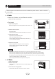
Part names and their functions
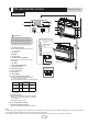
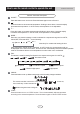
INDOOR UNIT
CAUTION
OPERATION INSTRUCTIONS
77℉
77℉
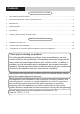
① If the supply cord is damaged, it must be replaced by the manufacturer or its service agent or a similarly qualified person in order to avoid a hazard.
③ An all-pole disconnection switch having a contact separation of at least 3mm in all poles should be connected in fixed wiring.
② The appliance shall be installed in accordance with national wiring regulations.
NOTE:
16
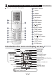
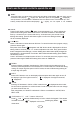
Air outlet selection switch
This setting blows air from
upper outlet only.
•
This setting automatically
decides a blow pattern
depending on mode and
conditions.
•
The unit is shipped from the
factory with this setting.
This setting is recommended.
12. Run lamp
13. LED display
16.Air outlet selection switch
17.Room temperature sensor:
● It senses the air temperature around the unit.
15.Signal receiver:
● It receives signals from the remote controller.
● When the unit receives a signal, you will hear
a short beep.
● Settings changed.....beep
14. Indoor Unit ON/OFF switch:
● Push this switch once to start operation.
Push once again to stop it.
2. Air outlet
3. Display
4. Front panel
5. Louvers (vertical blades)
● The louvers are inside of the air outlet.
6. Air inlet
7. Air filter
8. Flap (horizontal blade)
9. Cool mode lamp
10. Heat mode lamp
11. Dry mode lamp
● These filters are attached to the inside
of the air filters.
● The operation mode refers to the following table.
● This switch is useful when the remote controller
is missing.
Model Mode
Temperature
setting
Air flow rate
AUTO
AUTO
AUTO
AUTO
COOLING
ONLY
HEAT
PUMP
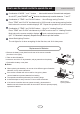
Opening the Front Panel
Indoor unit
wiring terminal
N(1) 2 3
3
9
12
10
14 15
13
11
1 2
5
6
2
4
7
8
Before opening the front panel, be sure to
stop the operation and turn the breaker OFF.
Do not touch the metal parts on the inside
of the indoor unit, as it may result in injury.
17
•
•
white
(blue)
black
red
(brown)
green
(yellow-
green)
Outdoor unit connection
1. Air-Purifying Filter: