Owner's Manual Original Instructions Floor Ceiling Type Air Conditioner Thank you for choosing our product. Please read this Owner’s Manual carefully before operation and retain it for future reference. If you have lost the Owner's Manual, please contact the local agent at 800-865-5931 or visit www.alpinehomeair.com.
BMKH09MFCC BMKH12MFCC BMKH18MFCC BMKH24MFCC
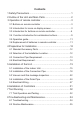
Contents 1 Safety Precautions............................................................... 1 2 Outline of the Unit and Main Parts ....................................... 2 3 Operation of remote controller................................................3 3.1 Buttons on remote controller ..................................................3 3.2 Introduction for icons on display screen..................................3 3.3 Introduction for buttons on remote controller...........................4 3.
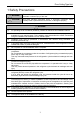
Floor Ceiling Type Unit 1 Safety Precautions WARNING! This mark indicates procedures which, if improperly performed, might lead to the death or serious injury of the user. CAUTION! This mark indicates procedures which, if improperly performed, might possibly result in personal harm to the user, or damage to property. WARNING! (1). For operating the air conditioner pleasantly, install it as outlined in this installation manual. (2).
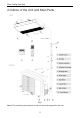
Floor Ceiling Type Unit 2 Outline of the Unit and Main Parts Fig.1 Notes: The connection pipe and duct for this unit should be prepared by the user.
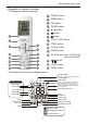
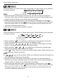
Floor Ceiling Type Unit 3 Operation of remote controller 3.1 Buttons on remote controller 2 3 4 ON/OFF button 2 MODE button 3 FAN button 4 TURBO button 5 ▲/ ▲ 1 1 button 6 button 7 button 8 T-ON / T-OFF button 9 I FEEL button 10 CLOCK button 5 11 SLEEP button 7 6 9 8 13 10 12 X-FAN button (Note: X-FAN is the same with BLOW.) button 13 14 11 14 LIGHT button 15 12 15 TEMP button 3.2 Introduction for icons on display screen { Set fan speed (No fan speed.
Floor Ceiling Type Unit 3.3 Introduction for buttons on remote controller Note: ● This is a general use remote controller, it could be used for the air conditioners with multifunction; For some function, which the model doesn't have, if press the corresponding button on the remote controller that the unit will keep the original running status. ● After putting through the power, the air conditioner will give out a sound.
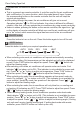
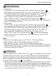
Floor Ceiling Type Unit Note: ● For preventing cold air, after starting up heating mode, indoor unit will delay 1~5 minutes to blow air (actual delay time is depend on indoor ambient temperature). ● Set temperature range from remote controller: 16~30℃(61-86°F); Fan speed: auto, low speed, medium speed, high speed. 3 FAN button Pressing this button can set fan speed circularly as: auto (AUTO), low( ( ), high( ).
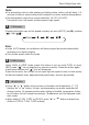
Floor Ceiling Type Unit 6 button Press this button can select left & right swing angle. Fan blow angle can be selected circularly as below: no display (stops at current position) Note: ● Press this button continuously more than 2s, the main unit will swing back an forth from left to right, and then loosen the button, the unit will stop swinging and present position of guide louver will be kept immediately.
Floor Ceiling Type Unit 8 T-ON / T-OFF button ● T-ON button "T-ON" button can set the time for timer on. After pressing this button, " " icon disappears and the word "ON" on remote controller blinks. Press "▲" or " " button to adjust T-ON setting. After each pressing "▲" or " " button, T-ON setting will increase or decrease 1min. Hold "▲" or " " button, 2s later, the time will change quickly until reaching your required time. Press "T-ON" to confirm it. The word "ON" will stop blinking.
Floor Ceiling Type Unit 10 CLOCK button Press this button to set clock time. " " icon on remote controller will blink. Press "▲" or " " button within 5s to set clock time. Each pressing of "▲" or " " button, clock time will increase or decrease 1 minute. If hold "▲" or " " button, 2s later, time will change quickly. Release this button when reaching your required time. ▲ ▲ ▲ Note: ● Clock time adopts 24-hour mode. ● The interval between two operation can’t exceeds 5s.
Floor Ceiling Type Unit 14 LIGHT button 15 TEMP button Press this button to turn off display light on indoor unit. " " icon on remote controller disappears. Press this button again to turn on display light. " " icon is displayed. By pressing this button, you can see indoor set temperature, indoor ambient temperature or outdoor ambient temperature on indoor unit’s display.
Floor Ceiling Type Unit be adjusted. ● Under energy-saving function, set temperature can’t be adjusted. Press "TURBO" button and the remote controller won’t send signal. ● Sleep function and energy-saving function can’t operate at the same time. If energy-saving function has been set under cooling mode, press sleep button will cancel energy-saving function. If sleep function has been set under cooling mode, start up the energy-saving function will cancel sleep function.
Floor Ceiling Type Unit About Back-lighting Function 3.5 Operation guide 1. After putting through the power, press "ON/OFF" button on remote controller to turn on the air conditioner. 2. Press "MODE" button to select your required mode: AUTO, COOL, DRY, FAN, HEAT. 3. Press "▲" or " " button to set your required temperature. (Temperature can’t be adjusted under auto mode). 4. Press "FAN" button to set your required fan speed: auto, low speed, medium speed, high speed. 5.
Floor Ceiling Type Unit 4 Preparative for Installation 4.1 Standard Accessory Parts The standard accessory parts listed below are furnished and should be used as required. Table 1 Indoor Unit Accessories No. Name 1 Nut with Washer 2 Wireless Controller + Battery 3 Appearance Q'ty 8 Usage To fix the hook on the cabinet of the unit.
Floor Ceiling Type Unit 4.2.1 Indoor Unit (1). Install the unit at a place where is strong enough to withstand the weight of the unit. (2). The air inlet and outlet of the unit should never be clogged so that the airflow can reach every corner of the room. (3). Leave service space around the unit as required in Fig. 2 (in) (59.05) (11.8) (11.8) (39.37) (11.8) (5.9) (11.8) (11.8) (11.8) (59.05) (90.55) Fig. 2 (4). Install the unit where the drain pipe can be easily installed. (5).
Floor Ceiling Type Unit Table 2 Max. Height Difference between Indoor Unit and Outdoor Unit (m) Indoor unit Drainage pipe(Outer Diameter × wall thickness) (in) Liquid Gas Max. Pipe Length (m) BMKH09MFCC 1/4 3/8 65 32 Φ17×0.068 BMKH12MFCC 1/4 1/2 65 32 Φ17×0.068 BMKH18MFCC 1/4 1/2 65 32 Φ17×0.068 BMKH24MFCC 3/8 5/8 65 32 Φ17×0.068 Item Model Size of Fitting Pipe(Inch) (1). The connecting pipe should be thermally insulated properly. (2). The pipe wall thickness shall be .019-.
Floor Ceiling Type Unit 5 Installation of the Unit 5.1 Installation of the Indoor Unit 5.1.1 Indoor unit dimension WARNING ! ①. Install the indoor unit in a location which can withstand a load of at least five times the weight of the main unit and which will not amplify sound or vibration. ②. If the installation location is not strong enough, the indoor unit may fall and cause injuries. ③. If the job is done with the panel frame only, there is a risk that the unit will come loose. Please take care.
Floor Ceiling Type Unit Unit: in Table 4 Model A B C D H BMKH09MFCC BMKH12MFCC 34.25 9.25 31.96 12.51 26.18 47.24 9.25 44.96 12.51 26.18 BMKH18MFCC BMKH24MFCC 5.1.2 Preparation for Installing the Indoor Unit (1). Open the air inlet grille and the screw cover, and remove the screws. (2). Release the claws in the 3 places indicated. (3). Release the center hook and remove the front panel. (4). Release the claws in the 2 or 3 places indicated and remove the electric component cover. 5.1.
Floor Ceiling Type Unit (5). Adjust the height of the unit to make the drain pipe slant slightly downward so that the drainage will become much smoother. ◆Floor type Fig. 5 ◆Ceiling type Fig. 6 (6). Reinstall and tighten the right and left side panel.
Floor Ceiling Type Unit 5.1.4 Leveling The water level test must be done after installing the indoor unit to make the unit is horizontal, as shown below. Fig. 7 5.2 Installation of the Connection Pipe 5.2.1 Flare Processing (1). Cut the connection pipe with the pipe cutter and remove the burrs. (2). Hold the pipe downward to prevent cuttings from entering the pipe. (3).
Floor Ceiling Type Unit 5.2.2 Bending Pipes (1). The pipes are shaped by your hands. Be careful not to collapse them. Fig. 9 (2). Do not bend the pipes in an angle more than 90°. (3). When pipes are repeatedly bent or stretched, the material will harden, making it difficult to bend or stretch them any more. Do not bend or stretch the pipes more than three times. (4). When bending the pipe, do not bend it as is. The pipe will be collapsed.
Floor Ceiling Type Unit 5.2.3 Connecting the Pipe at the Indoor Unit Side Detach the caps and plugs from the pipes. CAUTION! ①. Be sure to apply the pipe against the port on the indoor unit correctly. If the centering is improper, the flare nut cannot be tightened smoothly. If the flare nut is forced to turn, the threads will be damaged. ②. Do not remove the flare nut until the connection pipe is to be connected so as to prevent dust and impurities from coming into the pipe system.
Floor Ceiling Type Unit Pipe Diameter Tightening Torque 1/4〞(Inch) 15-30 (N·m) 3/8〞(Inch) 35-40 (N·m) 1/2〞(Inch) 45-50 (N·m) 5/8〞(Inch) 60-65 (N·m) 3/4〞(Inch) 70-75 (N·m) 7/8〞(Inch) 80-85 (N·m) CAUTION! Be sure to connect the gas pipe after connecting the liquid pipe completely. 5.2.4 Connecting the Pipe at the Outdoor Side Unit Tighten the flare nut of the connection pipe at the outdoor unit valve connector. The tightening method is the same as that as at the indoor side Fig. 13 5.2.
Floor Ceiling Type Unit 5.2.7 Liquid Pipe and Drain Pipe (1). If the outdoor unit is installed lower than the indoor unit. (See Fig. 15) 1). A drain pipe should be above ground and the end of the pipe does not dip into water. All pipes must be restrained to the wall by saddles. 2). Taping pipes must be done from bottom to top. 3). All pipes are bound together by tape and restrained to wall by saddles. Fig. 15 (2). If the outdoor unit is installed higher than the indoor unit. 1).
Floor Ceiling Type Unit 5.3.1 Vacuum (1). Remove the caps of the liquid valve, gas valve and also the service port. (2). Connect the hose at the low pressure side of the manifold valve assembly to the service port of the unit’s gas valve, and meanwhile the gas and liquid valves should be kept closed in case of refrigerant leak. (3). Connect the hose used for evacuation to the vacuum pump. (4). Open the switch at the lower pressure side of the manifold valve assembly and start the vacuum pump.
Floor Ceiling Type Unit Fig. 17 Note: For the large-sized unit, it has the service port for both the gas valve and the liquid valve. During evacuation, it is available to connect two hoses of the manifold valve assembly to two service ports to quicken the evacuating speed. 5.4 Installation of the Drain Pipe 5.4.1 Precautions When Doing the Piping Work CAUTION! Install the drain hose in accordance with the instructions in this installation manual and keep the area warm enough to prevent condensation.
Floor Ceiling Type Unit (1). Keep piping as short as possible and slope it downwards at a gradient of at least 1/100 so that air may not remain trapped inside the pipe. (2). Keep pipe size equal to or greater than that of the connecting pipe. (3). Install the drain piping as shown and take measures against condensation. Improperly rigged piping could lead to leaks and eventually wet furniture and belongings. Fig. 19 (4). Connect the drain hose.(Fig. 20) Fig. 20 5.4.2 Installing the Drain Pipes (1).
Floor Ceiling Type Unit Fig. 21 Fig. 22 Fig. 23 Tighten the clamp until the screw head is less than 4 mm from the hose. (Fig. 22) ①- Metal clamp ②- Drain hose ③- Grey tape Insulate the pipe clamp and the drain hose using heat insulation sponge. (Fig. 23) ①- Metal clamp ②- Insulation sponge (1). When drain hose requires extension, obtain an extension hose commercially available. (2). After connecting the local drain hose, tape the slits of the heat insulation tube. (3).
Floor Ceiling Type Unit Fig. 24 5.4.4 Testing of Drain Piping (1). After piping work is finished, check if drainage flows smoothly. (2). As shown in the Figure, pour water into the drain pan from the right side to check that water flows smoothly from the drain hose. 5.5 Electrical Wiring Fig. 25 5.5.1 Wiring Precautions WARNING! ①. Before obtaining access to terminals, all supply circuits must be disconnected. ②. The rated voltage of the unit is as shown as Table 3 ③.
Floor Ceiling Type Unit ⑤. The special branch circuit breaker is installed in the permanent wiring. Always use a circuit that can trip all the poles of the wiring and has an isolation distance of at least 3 mm between the contacts of each pole. ⑥. Perform wiring work in accordance with standards so that the air conditioner can be operated safely and positively. ⑦. Install a leakage special branch circuit breaker in accordance with the related laws and regulations and electric company standards.
Floor Ceiling Type Unit Fig. 26 Fig. 27 Fig. 28 (3). How to fix connection cord and power cord by cord clamp After passing the connection cord fasten it with the cord clamp. (Fig. 28) WARNING! ①. Before starting work, check that power is not being supplied to the indoor unit and outdoor unit. ②. Match the terminal block numbers and connection cord colors with those of the indoor unit side. Erroneous wiring may cause burning of the electric parts. ③. ④.
Floor Ceiling Type Unit (4).
Floor Ceiling Type Unit (5). Electric wiring of indoor unit side Remove the left cover plate and the electric box cover then insert the end of the communication cord and the power cable into the terminal board. Electric box cover Left side panel Fig. 30 CAUTION! ①. Tighten the power cord respectively on the terminal boards with screws. Faulty connection may cause a fire. ②. If the power supply are wired incorrectly, the air conditioner may be damaged. ③.
Floor Ceiling Type Unit 7 Test Running 7.1 Trial Operation and Testing The meaning of error codes as shown below: (1).
Floor Ceiling Type Unit States of the Indicating Lamps: ①. Indicating Lamp of “POWER”: The indicating lamp will shine when power on, while it will go out when power off. ②. Indicating Lamp of “COOL” : The indicating lamp will shine when “COOL” is activated, while it will go out when “COOL” is deactivated. ③. Indicating Lamp of “HEAT”: The indicating lamp will shine when “HEAT” is activated, while it will go out when “HEAT” is deactivated. ④.
Floor Ceiling Type Unit 8 8 9 ① ② ③ ④ ① ② ③ (114.8°F). ① ② ③ ④ ⑤ ⑥ ⑦ ① ② ③ ④ ⑤ ⑥ (23°F).
Floor Ceiling Type Unit 8.2 Routine Maintenance WARNING! ①. Do turn off the unit and cut off the main power supply when cleaning the air conditioner, otherwise electric shock may happen. ②. Do not make the air conditioner wet or electric shock may be lead; Ensure that the air conditioner will not be cleaned by water rinsing under any circumstance. ③. Volatile liquid like thinner or gasoline would damage the appearance of air conditioner.