
Ultra heat multi-zone ODU user manual


INSTALLING THE OUTDOOR UNIT INSTALLER
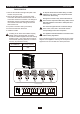
BLEEDING INSTALLER
10
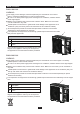
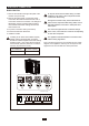
Do not install the outdoor unit in pits or air vents
Installing the pipes
Use suitable connecting pipes and equipment for
the refrigerant R410A.
Tighten the connections using two wrenches wor-
king in opposite directions.
The refrigerant pipes must not exceed the maximum
heights 10m(18Kx2&24Kx2&24Kx3&36x2&36x3&36
x4&42x2&42x3&42x4&42x5).
Wrap all the refrigerant pipes and joints.
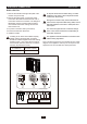
Vacuum pump
(1) Unscrew and remove the caps from the 2-way and 3-
Humid air left inside the refrigerant circuit can cause com-
pressor malfunction. After having connected the indoor
and outdoor units, bleed the air and humidity from the
refrigerant circuit using a vacuum pump.
way valves.
(2) Unscrew and remove the cap from the service valve.
(3) Connect the vacuum pump hose to the service valve.
(4) Operate the vacuum pump for 10-15 minutes until an
low-pressure knob on the vacuum pump coupling.
absolute vacuum of 10 mm Hg has been reached.
(5) With the vacuum pump still in operation, close the
Stop the vacuum pump.
(6) Open the 2-way valve by 1/4 turn and then close it
after 10 seconds. Check all the joints for leaks using
liquid soap or an electronic leak device.
Vacuum pump Vacuum pump
Location
(7) Turn the body of the 2-way and 3-way valves. Discon-
nect the vacuum pump hose.
(8) Replace and tighten all the caps on the valves.
conversion joint
18、24、36、42K
Connect to the
indoor unit
INDOOR
UNIT
Refrigerant fluid di
rection of fiow
3-way valve
inlet
2-w
ay valve
(8) Secure
(2)Turn
(7)Turn to open fully
(8) Secure
(2)Turn
(6) Open by 1/4 turn
(7)Turn to open fully
(8) Secure
(2)Turn
Valve cap
V
alve cap
Service
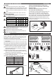
Use bolts to secure the unit to a flat, solid floor.
When mounting the unit on a wall or the roof, make
sure the support is firmly secured so that it cannot
move in the event of intense vibrations or a strong
wind.
Caution: Installation Must be Performed in
Accordance with the NEC/CEC by Authorized
Personnel Only.
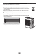
Install the drain fitting and the drain hose
(for model with heat pump only)
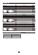
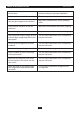
36Kx3
Max. connection pipe length
50
Models(m) 18Kx2 24Kx2 24Kx3 36Kx2
25
Condensation is produced and flows from the out-
door unit when the appliance is operating in the
heating mode. In order not to disturb neighbours
and to respect the environment,install a drain fitting
and a drain hose to channel the condensate water.
Install the drain fitting and rubber washer on the
outdoor unit chassis and connect a drain hose to it
as shown in the figure.
50
25
50
25
70
25
75
25
36Kx4 42Kx4
Max. connection pipe length
(Simple one indoor unit)
Models(m) 42Kx5
Max. connection pipe length
75
Max. connection pipe length
(Simple one indoor unit)
25
42Kx2 42Kx3
50
25
80
25
75
25
80
25
unit need to be installed the indoor unit
Twisting moment (N.m)
35-40
60-65
45-50
1/2''
Diameter
3/8''
5/8''
15-201/4''
3/4'' 70-75