RESIDENTIAL BURNERS Potential for Fire, Smoke and Asphyxiation Hazards Incorrect installation, adjustment, or misuse of this burner could result in death, severe personal injury, or substantial property damage. To the Homeowner or Equipment Owner: y Please read and carefully follow all instructions provided in this manual regarding your responsibilities in caring for your heating equipment. y Contact a professional, qualified service agency for installation, start-up or service work.
To the Owner: Thank you for purchasing a Beckett burner for use with your heating appliance. Please pay attention to the Safety Warnings contained within this instruction manual. Keep this manual for your records and provide it to your qualified service agency for use in professionally setting up and maintaining your oil burner. Your Beckett burner will provide years of efficient operation if it is professionally installed and maintained by a qualified service technician.
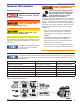
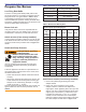
Section: General Information General Information Owner’s Responsibility Hazard Definitions Indicates a hazardous situation, which, if not avoided, will result in death or serious injury. Indicates a hazardous situation, which, if not avoided, could result in death or serious injury. Incorrect installation, adjustment, and use of this burner could result in severe personal injury, death, or substantial property damage from fire, carbon monoxide poisoning, soot or explosion.
Section: General Information Do NOT Alter the Original Burner Design Tampering with or altering the burner design could seriously impair performance, resulting in loss of static pressure, damage to the system components, reduced air volume, heavy smoke, flame impingement, appliance sooting, hot gas puff-back, and asphyxiation or fire hazards. Maintain the design to its original configuration. Only use parts specified for AF or AFG Burners. Do NOT remove the air guide from the AFG chassis.
Section: General Information Table 2 – Air Tube Combination (ATC) codes ATC Codes for usable air tube lengths (‘A’ in inches; See Figure 3.) Firing Rate (gph) (min-max) Head Static plate size (inches) Venturi 0.50-0.75 F0 3-3/8U None 0.75-1.25 F3 2-3/4U None AF44XN - 0.85-1.
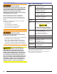
Section: Inspect/Prepare Installation Site Inspect/Prepare Installation Site Inspect Chimney or Direct Vent System piece of broken tile wedged in the chimney should be removed. 5. No other appliance connection should be made to the same flue pipe. Fire, Smoke & Asphyxiation Hazard 6. The flue pipe should have an upward pitch toward the chimney of at least 1/4” per foot of length. It should fit tightly and should not project into the chimney. y Carefully inspect the chimney or exhaust vent system.
Section: Inspect/Prepare Installation Site Combustion air supply Adequate Combustion and Ventilation Air Supply Required Failure to provide adequate air supply could seriously affect the burner performance and result in damage to the equipment, asphyxiation, explosion or fire hazards. y The burner cannot properly burn the fuel if it is not supplied with a reliable combustion air source.
Section: Prepare the Burner Prepare the Burner Low Firing Rate Baffle The AFG Low Firing Rate Baffle (LFRB) reduces the air flow and pressure. The LFRB is sometimes used for firing rates under 1.00 gph as listed in Table 4. Refer to the appliance manufacturer’s instructions. Do not omit the LFRB when specified. Omitting the baffle when specified or installing the baffle when not specified could result in impaired burner performance.
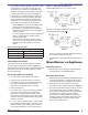
Section: Mount Burner on Appliance 3. If the nozzle is already installed, remove the nozzle line assembly to verify that the nozzle size and spray pattern are correct for the application (per appliance manufacturer’s information). Verify that the electrode tip settings comply with Figure 3. Figure 3. – Electrode Tip Adjustment Standard Dimensions for F, L1, and V1 Heads. 4.
Section: Mount Burner on Appliance Figure 4.
Section: Mount Burner on Appliance Figure 5. Check/Adjust ‘Z’ Dimension - L1 & L2 Heads 2. Use the following procedure to adjust the “Z” dimension, if it is not correct: ○ ○ ○ ○ ○ ○ L1/L2 heads (see Table 7 and Figure 3 for dimensions) 1. See figure above. The important “Z” dimension is the distance from the leading edge of the head to the end of the air tube. This distance for L1 & L2 heads is 1-3/8” if the tube has a straight shroud or 1-3/4” if the air tube has a conic shroud.
Section: Mount Burner on Appliance Figure 7. – Mounting Burner in Appliance Figure 8. – Inside Tank Gravity Feed System If space between burner air tube and opening exceeds 1/2 inch, pack burner opening with ceramic fiber refractory. Tilt down 2° SK8745 Installing the Oil Tank and Supply System Oil Leak and Fire Hazard Install the oil tank following applicable standards in the U.S. by referring to the latest edition of NFPA 31 or CSA-B139 & CSA-B140 in Canada, and all authorities having jurisdiction.
Section: Wire Burner Oil Supply Pressure Control Required Damage to the filter or pump seals could cause oil leakage and a fire hazard. Wire burner Burner packaged with appliance Electrical Shock Hazard y The oil supply inlet pressure to the burner cannot exceed 3 psig. Electrical shock can cause severe personal injury or death. y Insure that a pressure limiting device is installed in accordance with the latest edition of NFPA 31. y Do NOT install valves in the return line. (NFPA 31, Chapter 8.
Section: Burner Controls Burner Controls Wiring GeniSys Model 7505 Control Fire or Explosion Hazard Can cause severe injury, death, or property damage. y The control can malfunction if it gets wet, leading to accumulation of oil or explosive oil vapors. y Never install where water can flood, drip or condense on the control. y Never use a control that has been wet - replace it.
Section: Burner Controls Typical Burner Sequence of Operation for GeniSys 7505 Control. Refer to the appliance manufacturer’s wiring diagram for actual specifications. 9 1 Pump prime Standby 3 2 4 Trial for ignition Valve-on delay Lockout 5 Ignition carryover 6 8 Motor-off delay 1. Standby: The burner is idle, waiting for a call for heat. 2. Valve-On Delay: The igniter and motor are on while the control delays turning on the oil solenoid valve for the programmed time. 3.
Section: Burner Controls 60 70 SAFETY AND OPERATING LIMITS L1 R L2 60 70 60 70 W SAFETY AND OPERATING LIMITS 80 50 60 50 80 L2 W 80 50 L1 Figure 11b. – Interrupted ignition, valve-on delay and motor-off delay 70 R 50 80 Figure 11a.
Section: Burner Controls Figure 10 - Typical Burner Wiring & Burner Sequence of Operation for R7184P Control. Refer to the appliance manufacturer’s wiring diagram for actual specifications. 1. STANDBY. The burner is idle, waiting for a call for heat. When a call for heat is initiated, there is a 310 second delay while the control performs a safe start check. 2. VALVE-ON DELAY. The ignition and motor are turned on for a 15 second valve-on delay. 3. TRIAL FOR IGNITION (TFI). The fuel valve is opened.
Section: Start-up Burner/Set Combustion Wire Burner 3. Set the thermostat substantially above room temperature. Some Thermostats Are Polarity Sensitive. Reversed polarity could cause erratic cycling of the burner control. Connect the wire from the RH or R terminal on the thermostat to the TR terminal on the control. Connect the wire from the W terminal on the thermostat to the TW terminal on the control. 4. Close the line voltage switch to start the burner.
Section: Start-up Burner/Set Combustion ○ ○ mode. Verify that the green light is flashing. The control will remain in Recycle for 60 seconds. Always verify the control functions according to all specifications before leaving the installation site. Replace the control if it does not operate as specified. 4. After the 60 second recycle period, the control will try to restart the system. 5. After the 15 second lockout time, the control will lock out the burner and the reset button will flash.
Section: Perform Regular Maintenance Step 4: Recheck smoke level. It should be Zero. This procedure provides a margin of reserve air to accommodate variable conditions. If the draft level has changed, recheck the smoke and CO2 levels and readjust the burner if necessary. 4. Once combustion is set, tighten all fasteners on air band, air shutter and head adjusting plate or escutcheon plate. 5. Burner equipped with cover - Reinstall the cover and repeat Steps 2 and 4.
Section: Perform Regular Maintenance Replace the blower wheel: 1. Turn off all power to the burner before servicing. Figure 12. Blower wheel assembly 2. Disconnect the burner motor wires. 3. Remove the bolts securing the motor to the burner housing. 4. Remove the motor and blower wheel. 5. Remove the existing blower wheel. Use a Feeler Gauge to set the gap to; AF = 0.125 +1/64 inch AFG = 0.030 +1/64 inch 6. Referring to the figure below, slide the new blower wheel onto the shaft.
For best performance specify genuine Replacement Parts Beckett replacement parts These parts are unique to AF burners. Replace parts numbered 11 and 12 with the exact parts designated in the parts list.
AFG Burner Manual 23 Escutcheon (F & L1/L2 heads) Head Adjusting Plate (V1 head) Specify* 21807U 21887U 2184404U 5394 3666 3493 5941 3 4 Not Shown 5 6 7 8 Replaces R7184P - Pre and Posttime** 21805U 4189 5770 7505A 7505B 7505P 13 14 15 51771U Replaces R7184B - Pre-time 2999U (AFG) 2459U (AF) 12 16 Replaces R7184A - Interrupted Ignition 31231U (AFG) 31841U (AF) 11 Igniter & Base Plate Electrical Box PSC Motor Mounting Screws Blower Wheel (AFG) Blower Wheel (AF) Air Guid
Limited Warranty Information The R. W. BECKETT CORPORATION (“Beckett”) warrants to persons who purchase its “Products” from Beckett for resale, or for incorporation into a product for resale (“Customers”), that its equipment is free from defects in material and workmanship. To qualify for warranty benefits, products must be installed by a qualified service agency in full compliance with all codes and authorities having jurisdiction, and used within the tolerances of Beckett’s defined product specifications.