
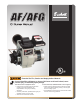
Beckett Burner Manual


4
Section: General Information
Do NOT Alter the Original
Burner Design
Tampering with or altering the burner design could
seriously impair performance, resulting in loss of
static pressure, damage to the system components,
reduced air volume, heavy smoke, fl ame
impingement, appliance sooting, hot gas puff-back,
and asphyxiation or fi re hazards.
Maintain the design to its original confi guration.
Only use parts specifi ed for AF or AFG Burners.
Do NOT remove the air guide from the AFG chassis.
Do NOT use ‘M’ Series air tube combinations on AF
Burners.
Never try to convert an AF to an AFG or vice versa
Any design alteration will:
Void UL Listing
Void manufacturer’s warranties
Seriously impact burner performance
Greatly increase your liability risk
y
y
y
y
Impaired Burner Performance
and Fire Hazard.
Do NOT operate the burner beyond specifi cations
outlined in the following Table.
For applications beyond these limits, consult Beckett
Technical Service at 1-800-645-2876.
NOTE: Some packaged appliances with burners
may be agency listed as a unit to operate beyond
these limits. Consult the appliance manufacturer’s
specifi cations and agency approvals for verifi cation.
y
y
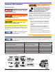
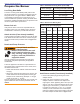
Table 1 – Burner Specifi cations
Capacity
(Note 1)
‘F’ Head (AF & AFG)
Firing rate range: 0.40 – 3.00 GPH
Input: 56,000 – 420,000 Btu
‘L1’ Head (AFG Only)
Firing rate range: 0.40 - 1.10 GPH
Input: 56,000 – 154,000 Btu/h
‘L2’ Head (AFG Only)
Firing rate range: 0.50 - 1.00 GPH
Input: 70,000 – 140,000 Btu/h
‘V1’ Head (AFG Only)
Firing rate range: 0.75 - 2.75 GPH
Input: 105,000 – 385,000 Btu/h
Certifi cations/
Approvals
UL listed to comply with ANSI/UL296 and CSA-
B140.0
Fuels
USA: No. 1 or No. 2 heating oil only (ASTM D396)
Canada: No. 1 stove oil or No. 2 furnace oil only
DO NOT USE GASOLINE, CRANKCASE
OIL, OR ANY OIL CONTAINING GASOLINE.
Electrical
Power supply: 120 volts AC, 60 Hz single phase
Operating load: 5.8 Amps max
Motor: 1/7 hp, 3450 rpm, NEMA 48M frame PSC
rotation CCW when facing shaft end
Ignition: Continuous duty solid-state igniter
Fuel pump
Outlet pressure: Note 2
Air tube
ATC code: See Table 2
Dimensions
(with cover)
Height (maximum): 12.5 inches
Width (maximum): 15 inches
Depth: 9.25 inches
Air tube diameter: 4.00 inches
Ambient Operat-
ing Temperature
+32
o
F. (0 C.) Minimum
+115
o
F. (+46 C.) Maximum
(See above Warning)
Moisture
5% to 95% RH, non-condensing and non-crystallizing
Note 1: Approval agency listed rating for these burners is 0.40 to 3.00
gph. However, the fi ring rate range is limited by the specifi c air tube
combination being used. Refer to Table 2.
Note 2: See appliance manufacturer’s burner specifi cations for
recommended pump discharge pressure.
If the residence is unattended in severely cold
weather, burner primary control safety lockout,
heating system component failures, power outages
or other electrical system failures could result in
frozen plumbing and water damage in a matter of
hours. For protection, take preventive actions such
as having a security system installed that operates
during power outages, senses low temperature
and initiates an effective action. Consult with your
heating contractor or a home security agency.
Frozen Plumbing and
Water Damage Hazard