
PTAC Owners and Installation Manual

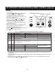
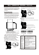
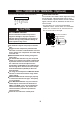
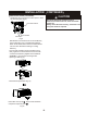
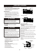
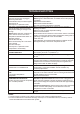
Table Of Contents

10
(Optional)WALL THERMOSTAT TERMINAL
IMPORTANT: Only trained, qualified personnel
should access electrical panel on unit and install
electrical accessories. Please contact your local
electrical contractor, dealer, or distributor for
assistance.
Thermostat Wire Routing
Thermostat wire is field supplied. Recommended
wire gauge is 18 to 20 gauge solid thermostat wire.
NOTE: It is recommended that extra wires are run
to unit in case any are damaged during installation.
Thermostat wire should always be routed around
or under, NEVER through, the wall sleeve. The
wire should then be routed behind the front panel
to the easily accessible terminal connector.
THERMOSTAT WIRE ROUTING
(UNDER SLEEVE, BEHIND FRONT PANEL)
Fig. A - Proper Wire Routing Beneath Unit
NOTE: Refer to thermostat installation instructions
for details on installing wall thermostat.
Installation instruction of some types of wall
(you can Consult with the
sales agency or manufacturer for details)
Thermostat
- Pull the dip switch to the DOWN(OFF) position as
shown below.
- Insert the wire connector of the wall t into
the relevant terminal according to different shapes as
shown below.
hermostat
Terminal of some types of wall
t hermostat
Installation instruction of PTAC other Wall
Thermostat
- Remove the two screws as shown below and take the cover
panel down.
Remove the two screws
Take the cover panel down
Terminal of PTAC other Wall
Thermostat
FC(L)
FC(N)
LOW-FAN
HI-FAN
4-WAY
HEAT2
HEAT1
COMP
24V(N)
24V(L)
TERMINAL
DESIGNATION
FC(L) Front desk control terminal L
FC(N)
Front desk control terminal N
LOW-FAN Low fan speed
HI-FAN
High fan speed
4-WAY
HEAT2
Electrical heater 2
HEAT1
Electrical heater 1
COMP
Compressor
24V(N)
24V(L)
24VAC terminal N(Neutral),Common
24VAC terminal L
4-way valve; Reverse cycle (Energized in
Heat) For heat pump models
Terminal of PTAC other Wall Thermostat(MODE A)
Dip switch
Dip switch