
BPRPGE14 Installation Instructions


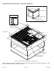

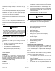


Table Of Contents

Page 10 of 19 507295B03Issue 2122
Venting
The vent outlet must be installed in a location as to prevent
building degradation and must be consistent with the
National Fuel Gas Code, Z223.1 or CAN/CGA-B149.1 &
.2.
The products of combustion are discharged through
a screened opening on the gas heat side panel. The
horizontal vent system shall terminate at least 4 feet below,
4 feet horizontally from, or 1 foot above any door, window,
or gravity air inlet into the building. The vent system shall
terminate at least 3 feet above any forced air inlet located
within 10 feet.
The unit shall be installed in a manner such that snow
accumulation will not restrict the ow of ue products.
Minimum horizontal clearance of 4 feet from electric meters,
gas meters, regulator, and relief equipment is required.
In addition to the above requirements, consideration must
be given to prevent unwanted ice buildup from the vent
condensate. The vent should not be located on the side of
a building where the prevailing winter winds could trap the
moisture, causing it to freeze on the walls or on overhangs
(under eaves). The vent should not be located over a
sidewalk, patio, or other walkway where the condensate
could cause the surface to become slippery.
The products of combustion must not be allowed to
accumulate within a conned space where they may
be recirculated.
Vent Hood Installation
The unit is shipped with the vent hood inside the control
compartment. Locate the vent hood and attach to side of
utility panel with screws provided in the instruction bag
(see Figure 2).
Vent Hood
A
ttach with
Screws
Figure 2. Installing the Vent Cover
2. All panels must be in place for rigging.
3. Place eld-provided spreaders in place. Spreaders
must be of adequate strength and length (must exceed
unit dimension by 6 inches).
Units may also be moved or lifted with a forklift. The
lengths of the forks of the forklift must be a minimum
of 42 inches.
Before lifting a unit, make sure that the weight is
distributed equally on the cables so that it will lift evenly.
CAUTION
Unpacking
Locate the four stacking brackets at each corner of the top
panel. Remove the screws that secure these brackets. All
screws must be re-installed. The stacking brackets can
be discarded. Remove the bag and remaining packaging
material, which can be discarded. Locate the four plastic
fork slot bumpers on the base rails. Remove the fasteners
and bumpers and discard.
Service Access
Access to all serviceable components is provided by four
removable panels: upper access panel (for blower, ID coil,
and optional lter), heat exchanger access, control access
panel, and compressor access.
As with any Mechanical equipment, personal injury can
result from contact with sharp sheet metal edges. Be
careful when you handle this equipment.
CAUTION
This unit is charged with HFC-410A refrigerant.
Operating pressures for units charged with HFC-410A
are higher than pressures in units charged with HCFC-
22. All service equipment MUST be rated for use with
HFC-410A refrigerant.
WARNING