
BPRPGE14 Installation Instructions


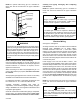
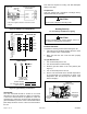
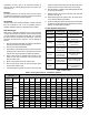
Table Of Contents

507295B03 Page 11 of 19Issue 2122
If an existing gas furnace is being removed from a
common venting system when this packaged unit is
installed, then read and follow the instructions in the
“Removal of Unit from Common Venting System” section
that follows. Otherwise, you may skip this section.
NOTE:
Removal of Unit from Common Venting System
When an existing furnace is removed from a common
venting system serving other appliances, the venting
system is likely to be too large to properly vent the
remaining attached appliances. The following test
should be conducted with each appliance while the other
appliances connected to the common venting system are
not in operation.
1. Seal any unused openings in the common venting
system.
2. Visually inspect the venting system for proper size and
horizontal pitch and determine there is no blockage
or restriction, leakage, corrosion, or other deciencies
which could cause an unsafe condition.
3. Insofar as is practical, close all building doors and
windows between the space in which the appliances
remaining connected to the common venting system
are located and other spaces in the building. Turn on
clothes dryers and any appliance not connected to the
common venting system. Turn on exhaust fans, such
as range hoods and bathroom exhausts, so they will
operate at maximum speed. Do not operate a summer
exhaust fan. Close replace dampers.
4. Following the lighting instructions, place the unit being
inspected in operation. Adjust the thermostat so the
appliance will operate continuously.
5. Test for spillage at the draft control relief opening after
5 minutes of main burner operation. Use the ame of
a match or candle.
6. Follow the preceding steps for each appliance
connected to the common venting system.
7. After it has been determined that each appliance
remaining connected to the common venting system
properly vents when tested as outlined above, return
doors, windows, exhaust fans, replace dampers,
and any other fuel burning appliance to their previous
condition of use.
8. If improper venting is observed during any of the
above tests, the common venting system must be
corrected. See National Fuel Gas Code, ANSI Z223.1
(latest edition) or CAN/CGA B149.1 & .2 Canadian
Installation Codes to correct improper operation of
common venting system.
Duct System
The duct system should be designed and sized according
to the methods in the Air Conditioning Contractors of
America (ACCA) manual that is most appropriate to the
installation application.
A closed return air duct system shall be used. This shall
not preclude use of economizers or outdoor fresh air
intake. It is recommended that supply and return air duct
connections at the unit be made with exible joints.
The supply and return air duct systems should be designed
for the CFM and static requirements of the job. They
should not be sized by matching the dimensions of the
duct connections on the unit.
The unit is shipped ready for horizontal ow (side duct
connections) or downow (bottom duct connections). All
units are equipped with a drain pan overow switch that is
installed and wired at the factory. Duct attachment screws
are intended to go into the duct panel anges. Duct to unit
connections must be sealed and weather proofed.
For horizontal duct systems:
1. Remove the duct covers on side of the unit. They can
be discarded.
2. Install the duct system to the unit.
For downow duct systems:
1. Remove the duct covers on side of the unit. Keep the
screws and the covers as they will be re-installed later.
2. Remove the downow duct covers located inside unit.
Remove the four screws securing each cover. Remove
the covers from the unit. They can be discarded.
3. Remove screws located between the supply and
return air openings that attach the blower deck to the
base pan. These screws can interfere with bottom duct
connections or roof curb seals. Discard these screws.
4. Install the duct system to the unit.
5. Re-install the duct covers removed in Step 1.
Filters
Air lters are not supplied with the unit. A eld-provided air
lter must always be installed ahead of the evaporator coil
and must be cleaned or replaced if necessary. Dirty lters
will reduce the airow of the unit.
An optional lter rack kit may be purchased separately
for installation inside the unit’s coil compartment. Air lter
sizes are shown in Table 2 for use with lter rack kit.
The lter rack must be installed prior to installation of
the unit in applications where access to the rear panel
is limited.
NOTE: