
BPRPGE14 Installation Instructions


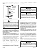
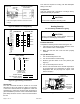
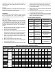
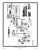
Table Of Contents

Page 12 of 19 507295B03Issue 2122
Gas Piping
Proper sizing of a gas piping depends on the cubic feet per
hour of gas ow required, specic gravity of the gas, and
length of run. National Fuel Gas Code Z223.1 latest edition
should be followed in all cases unless superseded by local
codes or gas company requirements. In Canada, refer to
CAN/CGA B.149.1 & .2 (latest edition).
The heating value of the gas may dier with locality. The
value should be checked with the local gas utility. For
temperature rise of unit, see unit rating plate.
Gas Piping Recommendations
• A drip leg and a ground joint union must be installed in
the gas piping. A ground joint union is recommended
by the manifold/valve.
• When required by local codes, a manual shuto valve
may have to be installed outside of the unit.
• Use pipe thread sealing compound resistant to
propane gas sparingly on male threads.
• The gas supply should be a separate line and installed
in accordance with all safety codes listed on Page
1. After the gas connections have been completed,
open the main shuto valve admitting normal gas
pressure to the mains. Check all joints for leaks
with soapy solution or other material suitable for the
purpose.
Never use a ame to check for gas leaks. Explosion
causing injury or death may occur.
WARNING
• The furnace and its eld supplied manual shuto valve
must be disconnected from the gas supply piping
system during any pressure testing of that system at
test pressures in excess of 1/2 PSIG (3.48kPa).
• A 1/8” N.P.T. plugged tapping, accessible for test
gauge connections, must be installed immediately
upstream of the gas supply connection to the furnace.
Gas Connection
The gas supply line is routed through the gas entry
location on the side of the unit (see Figure 4). A grommet is
provided in the instruction bag and should be used to seal
gas supply line to gas entry of control compartment.
Table 2. Unit Air Filter Sizes - inches
Unit Model Filter 1 Filter 2
24, 30, 36 14 x 20 x 1
20 x 20 x 1
42, 48, 60 20 x 20 x 1
Condensate Drain
This package unit is equipped with a 3/4” FPT coupling
for condensate line connection. Plumbing must conform
to local codes. Use a sealing compound on male pipe
threads.
Do not operate unit without a drain trap. The condensate
drain is on the negative pressure side of the blower;
therefore, air being pulled through the condensate line will
prevent positive drainage without a proper trap.
The condensate drain line must be properly trapped,
routed to a suitable drain and primed prior to unit
commissioning.
NOTE: Install drain lines and trap so they do not block
service access to the unit.
Figure 3. Typical Condensate Drain Connection
MINIMUM PITCH
1 IN (25) PER 10” (3048
MM) OF LINE
OPEN
VENT
UNIT
MOUNTING
FRAME
Trap must be deep enough to oset maximum static dierence
(generally, 3 inches (76 mm) minimum). In addition, the drain line
must be supported if longer than 10 feet.
Trap must be primed at start-up.
See Figure 3 for proper drain arrangement. The drain line
must pitch to an open drain or pump to prevent clogging
of the line. Seal around the drain connection with suitable
material to prevent air leakage into the return air system.
To prime trap, pour several quarts of water into drain,
enough to ll drain trap and line.
Drain lines should be hand-tightened only. Do not use
tools to tighten tting into drain.
CAUTION