
BPRPGE14 Installation Instructions


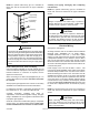
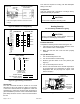
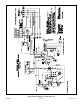
Table Of Contents

507295B03 Page 13 of 19Issue 2122
NOTE: An optional bottom-entry gas kit is available for
these units. See the kit instructions for proper installation
details.
Thermostat
Wire Entry
High Voltage
Power Entry
Gas Entry
Figure 4.
The furnace must be isolated from the gas supply piping
system by closing the eld supplied manual shuto valve
during any pressure testing of gas supply piping system
at test pressures equal to or less than 1/2 psig or 14”
w.c. If the piping system is to be tested at pressures in
excess of 1/2 psig, the furnace and its individual shuto
valve must be disconnected from the gas supply piping
system.
WARNING
NOTE: LP/Propane Units, Tanks, and Piping
Units are shipped equipped for use with natural gas, but
can be converted to LP/propane in the eld by an approved
licensed technician. If conversion is required, use the
approved conversion kit.
When converting a low NOx unit (designated by an L in
some model numbers) to propane, the NOx inserts must
be removed.
All LP/propane gas equipment must conform to the safety
standards of the National Fire Protection Association.
For satisfactory operation, LP/propane gas pressure must
be a minimum of 11” w.c. at the unit under full load.
Complete information regarding tank sizing for
vaporization, recommended regulator settings, and pipe
sizing is available from most regulator manufacturers and
LP/propane gas suppliers.
Check all connections for leaks when piping is completed,
using a soapy, non-chlorine based solution. Some soaps
used for leak detection are corrosive to certain metals.
Electrical Wiring
See Figure 4 and Figure 5
All wiring should be done in accordance with the National
Electrical Code, ANSI/NFPA No. 70 (latest edition);
Canadian Electrical Code Part 1, CSA C22.1 (latest
edition); or local codes where they prevail. Use wiring with
a temperature limitation of 75°C minimum. Run the 208 or
230 volt, 60 hertz electric power supply through a fused
disconnect switch to the control box of the unit and connect
as shown in the wiring diagram located on the inside of the
control access panel.
Power supply to the unit must be N.E.C. Class 1, and
must comply with all applicable codes. A disconnect switch
should be eld provided for the unit; follow local codes to
determine what type of switch to use. The switch must be
separate from all other circuits. If any of the wire supplied
with the unit must be replaced, replacement wire must be
of the type shown on the wiring diagram. Electrical wiring
must be sized to carry minimum circuit ampacity marked
on the unit. Use copper conductors only. Each unit must
be wired with a separate branch circuit and be properly
fused.
NOTE: An optional bottom-entry power kit is available for
these units. See the kit instructions for proper installation
details.
When connecting electrical power and control wiring
to the unit, waterproof type connectors must be used
so that water or moisture cannot be drawn into the unit
during normal operation.
CAUTION
Carefully rinse piping thoroughly after completing
leak detection.
NOTE: An optional bottom-entry gas kit is available for
these units. See the kit instructions for proper installation
details.
Danger of explosion. Can cause injury or product or
property damage. Do not use matches, candles, ame
or other sources of ignition to check for leaks.
WARNING
If a exible gas connector is required or allowed by
the authority that has jurisdiction, black iron pipe shall
be installed at the gas valve and must extend outside
the cabinet. The exible connector can then be added
between the black iron pipe and the gas supply line.
CAUTION