
BPRPGE14 Installation Instructions


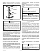
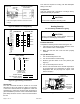
Table Of Contents

507295B03 Page 15 of 19Issue 2122
To Shut Down Main Burners
1. Turn o electrical power to unit.
2. Slide the gas valve switch to the “OFF” position (see
Figure 7).
Post-Start Checklist
After the entire control circuit has been energized and the
heating section is operating, make the following checks:
1. Check for gas leaks, using soapy solution, in the unit
piping as well as the supply piping.
2. Check for correct manifold gas pressures (see Manifold
Gas Pressure Adjustment Regulator sections).
3. Check the supply gas pressure. It must be within the
limits shown on the rating plate. Supply pressure
should be checked with all gas appliances in the
building at full re. At no time should the standby gas
pressure exceed 13” w.c., nor the operation pressure
drop below 5” w.c. for natural gas units or 11” w.c. for
propane gas. If gas pressure is outside these limits,
contact the gas supplier for corrective action.
4. Adjust temperature rise to the range specied on the
rating plate.
Manifold Gas Pressure Adjustment Regulator – Natural
Gas
For purpose of input adjustment, the minimum permissible
gas supply pressure is 5” w.c. for natural gas.
Gas input must never exceed the input capacity shown on
the rating plate. The furnace is equipped for natural gas
rated inputs with manifold pressure of 3.5” w.c.
The manifold pressure can be measured by shutting o
the gas, removing the pipe plug in the downstream side
of the gas valve, and connecting a water manometer
or gauge. Under no circumstances should the nal
manifold pressure vary more than 0.3” w.c. from the
above specied pressures. To adjust the regulator, turn
the adjusting screw on the regulator clockwise to increase
pressure and input or counterclockwise to decrease
pressure and input. See Figure 7 to assist in locating the
regulator on the gas valve.
Check the furnace rate by observing the gas meter, making
sure all other gas appliances are turned o. The test hand
on the meter should be timed for at least one revolution,
noting the number of seconds per revolution. The heating
value of the gas can be obtained from the local utility.
BTU/HR
Input
=
Cubic Feet per
Revolution
x 3600 x
Heating
Value
# Seconds per
Revolution
For example, by actual measurement, it takes 38 seconds
for the hand on the 1-cubic foot dial to make a revolution
with a 100,000 BTU/HR furnace running. The result is
99,750 BTU/HR, which is close to the 100,000 BTU/HR
rating of the furnace.
Manifold Gas Pressure Adjustment Regulator – LP/
Propane Gas
LP/propane units require a LPG regulator on both the gas
valve and on the LP/propane tank.
IMPORTANT: For purpose of input adjustment, the
minimum permissible gas supply pressure (inlet side of
gas valve) is 11” w.c. for LP/propane.
If at any time ignition is slow and burner does not seem to
be operating correctly, check manifold pressure (outlet side
of the gas valve). It should be 10” to 10.5” w.c. pressure
for LP/propane.
The furnace is designed to obtain rated input at 10”
w.c. manifold pressure for propane.
High Altitude
The input rate shown on the rating plate is for elevations
up to 2000 feet. For elevations from 2001 to 4500 feet,
the input rate is reduced by 5%. For elevations above
4500 feet, refer to the National Fuel Gas Code Z223.1
(latest edition) or the Canadian Installation Codes CAN/
CGA-B149.1 & B149.2 for further details.
To check this pressure:
1. Slide the gas valve switch to the “OFF” position (see
Figure 7).
2. Remove plug on valve marked “OUTLET PRESSURE.”
3. Install a water manometer.
4. Slide the gas valve switch to the “ON” position and
initiate a call for heat. If manifold pressure must be
adjusted, remove cap from pressure regulator and
turn adjustment screw clockwise to increase pressure
or counterclockwise to reduce pressure.
5. After checking pressure, turn gas o, remove
manometer tting, and replace pipe plug and regulator
cap.
6. Put furnace in operation and check plug for leaks
using soapy solution.
Burner and Burner Orice Instructions
To check or change burners or burner orices:
1. Close the main manual gas shuto valve and turn
o all power to unit.
2. Remove the burner access panel.
3. Disconnect the union in the gas supply line upstream
of the gas valve and downstream of the manual shuto
valve.
4. Label wires going to the gas valve, then disconnect
the wires.