
BPRPGE14 Installation Instructions


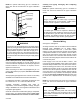
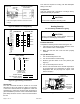
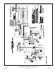
Table Of Contents

Page 16 of 19 507295B03Issue 2122
A combustion air inducer operates for the rst 10 seconds
of every cooling cycle to prevent insects from nesting in
the ue outlet.
Blower Delay – Cooling
The circulating air blower is controlled by a timing circuit
in the integrated blower/ignition control. Timings are not
adjustable. Blower “ON” delay is 5 seconds after the
compressor starts and blower “OFF” timing is 60 seconds
after the compressor shuts down.
NOTE: There is no blower OFF delay when there is a call
for G (fan only).
Cooling System Performance
This equipment is a self-contained, factory-optimized
refrigerant system. The unit should not require adjustments
to system charge when properly installed. If unit
performance is questioned, perform the following checks.
Cooling System Performance Values
Model
Suction
Superheat +/- 3°
Liquid
Subcooling +/- 2°
2 Ton 13
2.5 Ton 16
3 Ton 14
3.5 Ton 14
4 Ton 16
5 Ton 17
Based on outdoor ambient temperature of 82°F, and indoor
entering air of 80°F db, 67°F wb.
Table 3.
Ensure unit is installed per manufacturer’s instructions and
that line voltage and air ow are correct. Refer to Table 3
for proper performance value. The indoor metering device
varies by model. When checking performance of a unit
using an orice for metering, refer to the suction superheat
value to judge performance. When checking performance
of a unit that uses an expansion valve for metering, refer
to the subcooling value to judge system performance. If
the measured performance value varies from table value
allowance, check internal seals, service panels and duct
work for air leaks, as well as restrictions and blower
speed settings. If unit performance remains questionable,
remove system charge, evacuate to 500 microns, and
weigh in refrigerant to nameplate charge. It is critical that
the exact charge is re-installed. Failure to comply will
compromise system performance. If unit performance is
still questionable, check for refrigerant-related problems,
such as blocked coil or circuits, malfunctioning metering
device or other system components.
Continuous Fan
With the proper thermostat and sub-base, continuous
blower operation is possible by closing the R to G circuit.
Cooling blower delay is also functional in this mode.
5. To change orice:
a. Remove screws that fasten the manifold to the
burner box assembly and remove the manifold.
b. Remove the orices, then install replacement
orices.
c. To reassemble: Reverse above steps, making
sure orices are inserted into the orice holders
on the back end of the burners, and that burners
are level and centered on each burner opening in
the vest panel.
6. To remove or service burners:
a. Label and disconnect the wires to the rollout switch
and disconnect the igniter and ame sensor leads
at the ignition control.
b. Remove the screws that secure the burner box
assembly to the vest panel and remove the
assembly from the unit.
c. Remove the screws that fasten the burner rack
and bottom shield assembly to the burner box.
Burners are now accessible for removal.
d. To Reassemble: Reverse above steps.
7. After reassembly of all parts is complete and all wires
are reconnected, open the main manual gas shuto
valve; check for and correct any gas leaks. Turn
electrical power on, initiate a call for heat, and check
for proper burner operation.
8. Install burner access panel.
Heat Anticipator
The heat anticipator setting is 0.75 amp. It is important
that the anticipator setpoint be correct. Too high of a setting
will result in longer heat cycles and a greater temperature
swing in the conditioned space. Reducing the value below
the correct setpoint will give shorter “ON” cycles and
may result in the lowering of the temperature within the
conditioned space.
Operation
Cooling System
The cooling system is factory-charged with HFC-R-410A.
The compressor is hermetically sealed and base-mounted
with rubber-insulated bolts.
Cooling Sequence of Operation
When the thermostat calls for cooling, R is closed to Y (see
the wiring diagrams). This action completes the low voltage
control circuit, energizing the compressor, condenser fan
motor, and blower motor.
Unit compressors have internal protection. In the event there
is an abnormal rise in the temperature of the compressor,
the protector will open and cause the compressor to stop.