
BPRPGE14 Installation Instructions
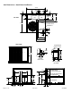


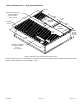
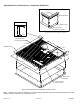

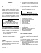


Table Of Contents

Page 6 of 19 507295B03Issue 2122
Top Edge
Wood Nailer Strip
Bottom Flange
Typical Slot
Typical Locking Ta b
See Cliplock 1000 installation instructions for complete
assembly and installation procedures and requirements.
NOTE:
CLIPLOCK CORNER DETAIL
CURB PROFILE
1
1/2
1-3/4
1
11-5/8
2-1/8
14
1
3-1/2
13-1/2
44-3/8
Bottom Curb
Assembly
Opening for Gas
Entry thru base
11-5/8
5-1/2
5-3/4
3-5/8
1-3/8
17-1/4
13-7/8
16-7/8
44-3/8
Insulated Panels
Opening for Power
Line Entry thru base
NOTE - Roof deck may be omitted within connes of curb.
NOTE - If bottom entry is used, condensate from the heat exchanger may leak during warm ambient temperatures in humid
climates. Ensure that bottom entry is watertight, if used.
Adjustable Roof Curb Dimensions - Small Base Gas/Electric