
BPRPGE14 Installation Instructions
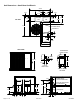


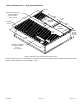
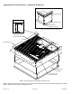

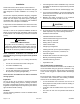


Table Of Contents

507295B03 Page 9 of 19Issue 2122
• Return air temperature range between 55°F (13°C)
and 80°F (27°C) must be maintained.
• Air lters must be replaced and pre-lters must be
removed upon construction completion.
• The input rate and temperature rise must be set per
the unit rating plate.
• The heat exchanger, components, duct system, air
lters and evaporator coil must be thoroughly cleaned
following nal construction clean-up.
• The unit operating conditions (including airow,
cooling operation, ignition, input rate, temperature
rise and venting) must be veried according to these
installation instructions.
Clearances
All units require certain clearances for proper operation
and service. Refer to Table 1 for the minimum clearances
to combustibles, servicing, and proper unit operation. In
the U.S., units may be installed on combustible oors
made from wood or class A, B, or C roof covering material.
In Canada, units may be installed on combustible oors.
Units must be installed outdoors.
Clearance to combustibles below the unit ue is 10 inches
since the ue points down.
Do not permit overhanging structures or shrubs to
obstruct condenser air discharge outlet, combustion
air inlet, or vent outlet.
Clearance to
Combustibles
Clearance for
Service Access
Front of unit 0 in. 24 in.
Back of unit 0 in. 0 in.
Left side 0 in. 24 in.
Right side (from
vent hood)
12 in. 24 in.
Base of unit 0 in. 0 in.
Top of unit 0 in. 48 in.
Minimum clearance to combustible material below the ue
is 10 inches to allow proper dissipation of ue gasses and
temperatures. For any future service, installer must provide
access to screws of top and rear panels.
Table 1. Minimum Clearances
Roof Curb Installation
If a roof curb is used, follow the manufacturer’s installation
instructions and be sure that all required clearances are
observed (see Clearances section).
Prior to setting the unit on the roof curb, the shipping
bracket located underneath the unit must be removed.
Remove the two screws in the base rail (located on the
front and rear of the unit). The four screws and the bracket
can be discarded. See Figure 1.
Rigging Unit
Exercise care when moving the unit. Do not remove any
packaging until the unit is near the place of installation.
1. Connect rigging to the unit base rails using both holes
in each corner.
Shipping Bracket and Mounting Screws Must be
Removed for Rooftop or Downflow Application
Field-Provided Lifting
Spreaders Recommended
Figure 1.