Volume 1.
M O D E L 9 3 0 W I R E S T R I P P I N G M A C H I N E UNPACKING THE ITEM Caution: This machine is packed together with items that may be sharp, oily and overly heavy objects. Remove the machine from the packaging in a safe manner. Check to ensure all accessories are included with the item while unpacking. If any parts are found to be missing, contact the retailer as soon as possible. Do not throw away the packaging until the item is out of the guarantee period.
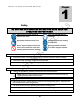
M O D E L 9 3 0 W I R E S T R I P P I N G M A C H I N E Table of Contents SAFETY 1 PRE-OPERATIONAL SAFETY CHECKS OPERATIONAL SAFETY CHECKS 1 1 SPECIFICATIONS 3 OPERATIONS 4 PURPOSE INSTALLATION OPERATIONAL PRINCIPLES MACHINE COMPONENTS PROCESSING WIRE WIRE TYPE GUIDE WIRE GUIDE DIAGRAM RUNNING WIRE 4 4 4 5 7 7 8 8 TROUBLESHOOTING 9 MAINTENANCE 10 CHANGING BLADES 10 PARTS LIST 12 BREAKDOWN VIEW 14
M O D E L 9 3 0 W I R E S T R I P P I N G 1 Chapter M A C H I N E Safety DO NOT USE THIS MACHINE UNLESS YOU HAVE READ THE OPERATING INSTRUCTIONS Safety glasses must be worn at all times in work areas. Long and loose hair must be contained. Appropriate footwear must be worn. Close fitting/protective clothing must be worn. Gloves, rings and jewelry must not be worn as wire could catch on the item and bring hands towards the machine. Hearing protection should be worn when using this machine.
M O D E L 9 3 0 W I R E S T R I P P I N G M A C H I N E Ø DO NOT make side-bolt centering adjustments while the machine is running. Ø DO NOT wear loose clothing or gloves as death or dismemberment can occur. When feeding wire/cable, gloves can snag on scrap wire and bring hand towards machine. Ø DO NOT touch moving parts while the machine is running. Ø DO NOT put cable/wire longer than 1 meter into machine. Ø DO NOT switch off the machine when it is under load, except in an emergency.
M O D E L 9 3 0 W I R E S T R I P P I N G M A C H I N E 2 Chapter Specifications ELECTRICAL DATA Voltage Current Motor Size Motor Starter O/P Power Connection MECHANICAL DATA Blades Cutting Assembly Cutting Speed Wire Cutting Range 120V, 60Hz 12.5 Amps 1.
M O D E L 9 3 0 W I R E S T R I P P I N G M A C H I N E 3 Chapter Operations Note THOROUGHLY READ THROUGH THE ENTIRE MANUAL BEFORE OPERATING THIS MACHINE! PURPOSE Ø The purpose of the 930 is to remove outer and inner jackets from wires and cables in order to separate the inner copper or aluminum. These types of machines are widely used in the recycling industry to extract copper and aluminum for recycling.
M O D E L 9 3 0 W I R E S T R I P P I N G M A C H I N E MACHINE COMPONENTS Ø The main components of the 930 are the central cutting and rolling assemblies. These are driven by a system of pulleys and belts, gears, sprockets, chains and motor. The safety guards are situated on top of the assemblies as well as in front where the wire guide is situated.
M O D E L 9 3 0 Ø W I R E S T R I P P I N G M A C H I N E The secondary adjusting point on this machine is the side centering bolts. These are the bolts with lock nuts on them located on the side of both bearing housings that adjust the top cutting assembly from right to left. o It is generally not recommended to adjust these bolts unless the smallest channel cutting blades are not centered in the cutting channel.
M O D E L 9 3 0 Ø W I R E S T R I P P I N G M A C H I N E The last main adjusting point on this machine are the lower mandible t-bolts. These are the bolts with lock nuts on them located on the bottom of all bearing housings. These adjust the top cutting assembly manually. Generally, do not adjust these lower T-bolts unless you are running oversized wire. If you do adjust them, only adjust the T-bolts on the right side (the large wire channel side).
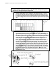
M O D E L 9 3 0 W I R E S T R I P P I N G M A C H I N E WIRE GUIDE DIAGRAM RUNNING WIRE Ø Do all pre-operational and operational safety checks from Chapter 1. Ø After securing the machine, plug the machine into power source. Ø Have your wires ready to process, by separating them by type and cutting them into 3-4’ lengths. o This is primarily for safety, but also to protect the motor from torque created by pulling heavy wires into the machine.
M O D E L 9 3 0 W I R E S T R I P P I N G M A C H I N E 4 Chapter Troubleshooting Problem Solution Wires get jammed in the machine There are a few possible fixes for this: 1) Loosen the top hand cranks to take pressure off springs to allow more room for the springs to depress. 2) Check to make sure you are running the wire through the right channel. This takes some time to figure out. Be patient when clearing the machine. Try the step down method. Start in a larger hole than you think.
M O D E L 9 3 0 W I R E S T R I P P I N G M A C H I N E 5 Chapter Maintenance Ø Inspect electrical cords and electrical connections. Ø Keep machine clean and free of debris. Ø Grease internal gears with red grease or Molybdenum grease as needed. Ø Spray antirust oil on spindle and blade shaft as needed. Ø Inspect blades occasionally to ensure they are sharp for optimal cutting. Ø Check and tighten up the belts occasionally. Changing Blades 1.
M O D E L 9 3 0 W I R E S T R I P P I N G M A C H I N E 7. Unscrew spanner nut clockwise. If you do not have a spanner nut wrench, it is possible to use a pair of vice grips. 8. MAKE SURE YOU MARK THE SPACERS 1 THROUGH 5 (OR 1 THROUGH 9 FOR THE TOP ASSEMBLY), SO THAT THEY GO BACK ON IN THE SAME ORDER THAT YOU TOOK THEM OFF. 9. Blades are ready to come off and be replaced. 10. When re-assembling put the bearing back into the bearing housing before attaching the housing to the cutter/roller. 11.
M O D E L 9 3 0 W I R E S T R I P P I N G M A C H I N E 6 Chapter Electrical Schematic 12
M O D E L 9 3 0 W I R E S T R I P P I N G M A C H I N E Parts List 1 2 3 4 5 6 7 8 9 10 11 12 13 14 15 16 17 18 19 20 21 22 23 24 25 26 Big side shield Output hopper Iron plate Hex bolt M10X110 Washer Φ Iron plate Galvanized support tube T shape handle M12 Wing nut M12 Small side shield Pressure cap Small spring 65Mn Big spring 65Mn Top shield Small siding board Spacer Front upper shaft Deep grove ball bearing Blades Main shaft Lower blade shaft B type belt L=1092 B type pulley Φ160 Feed inlet Switch
M O D E L 9 3 0 W I R E S T R I P P I N G M A C H I N E Breakdown View 14