Installation Instructions Remote Fans CFMR1000 & CFMR1400 Inline Blowers INLB300, INLB600 & INLB1200
PLEASE READ COMPLETE INSTRUCTIONS BEFORE PROCEEDING. INSTALLATION MUST COMPLY WITH ALL LOCAL CODES. Save these instructions for the local electrical inspector’s use. Please leave these instructions with this unit for the owner. Please retain the instructions for future reference. Turn power circuit OFF at the service panel and lock panel door before wiring this unit.
SAFETY PROCEDURES FOR INSTALLING YOUR NEW PRIZER HOOD (continued) CAUTION – To reduce the risk of fire, electric shock, or injury to people, observe the following: CAUTION – For general ventilation use only. Do not use to exhaust hazardous or explosive materials or vapors. 1. Installation work and electrical wiring must be done by a qualified installer in accordance with all applicable codes and standards, including re-rated construction. 2.
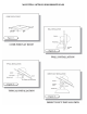
MOUNTING OPTIONS FOR REMOTE FANS
MOUNTING REMOTE FANS ON ROOF OR OUTSIDE WALL To prepare for mounting a remote fan, inspect the blower wheel to ensure it turns freely. Do not replace the top unit to the remote fan until the installation has been completed. A remote fan cannot be installed in a condition where the exhaust/discharge opening is less than 15” from the ground level. NOTE: There may be some local codes that will not permit this kind of installation. Heavy snow will prevent the damper from opening due to snow blockage.
CONNECTING THE 3-SPEED FAN CONTROL TO THE REMOTE FAN 1. Power supply required for remote fans are 15 amps. @ 120V. AC, 60Hz. connected per local codes. 2. Run three #14 AWG wires (black, white and green) from the power supply at the electrical circuit panel in the hood J-box (see Figure 6). 3. Run five wires from hood J-box through the walls to the remote fan, using color coded wires corresponding to color codes in diagram (see Figure 7. Page 6) 4.
WIRING A WALL-MOUNTED 3-SPEED FAN CONTROL 1. Use 4 Position switch (OFF – LOW – MED – HIGH). 2. Power supply required for these ventilators is 15 amps. @120V. AC, 60Hz. connected per local codes. 3. Run three #14 AWG wires (black, white and green) from the power supply at the electrical circuit panel to the wall box (see Figure 7). 4. Run electrical conduit per local code from wall box to bottom of remote fan as shown (see Figure 7). 5.
INLINE BLOWER INSTALLATION FOR INLB300, INLB600 & INLB1200 WARNING: ELECTRICAL CONNECTIONS SHOULD ONLY BE MADE BY A LICENSED ELECTRICIAN NOTE: All models use the same housing/enclose 1. Before making any electrical connection make sure your electric is turned off 2. Check that the fan’s impeller is moving freely 3. Unit is designed to be mounted in any position 4. For ideal implementation, close proximity of the blower to its discharge point will improve the unit’s performance 5.
INSTALLATION - POSITIONS WARNING 1. Use ¾” plywood to mount and separate from ceiling joists bed. 2. Install additional support cross members to truss for a suspended mount. 3. Install additional support cross members to truss for horizontal mounting. 4. Install additional blocking to mount under the roof rafter. 5. Install additional cross members to ceiling joists with a 90 degree elbow to exit side. Important Notes: • Adding plywood to each installation may simplify install.
INSTALLATION - SPECIFICATIONS
INSTALLATION MUST COMPLY WITH ALL LOCAL CODES KITCHEN VENTILATION TIPS WARNING – TO REDUCE THE RISK OF A RANGE TOP GREASE FIRE: 1. Cooking appliances such as ranges, cooktops, barbecue units, grill, etc, require adequate ventilation. Hood should be large enough and cooking appliances located so that the hood overhangs the cooking surface as much as possible. a) Never leave surface units unattended at high settings. Boil overs cause smoking and greasy spillovers that may ignite.