INSTALLATION MANUAL Column Refrigerator & Freezer Part # R-000046 revision 0 © Prizer Painter Stove Works, Blandon, PA 19510
Contents Safety Information 4 Site Preparation 6 Panel Preparation 8 Installation Instructions 10 Step 1—Uncrate and Inspect Product 10 Step 2—Remove Skid 10 Step 3—Hook up Electrical and Water 11 Step 4—Levelling 11 Step 5—Attach Plastic Connecting Brackets 11 Step 6—Install Two Appliances Side-by-Side 12 Step 7—Attach Wall Blocking 13 Step 8—Install Shoulder Bolts and Set Screws 13 Step 9—Install Panel (Panel-Ready Models) 14 Step 10—Move Appliance into Position 14 Step 11—Inst
Safety Information Please read and obey the following types of safety messages to ensure your refrigerator is installed and operated as safely as possible: DANGER Will cause serious injury or death if instructions are not followed. WARNING Can cause serious injury or death if instructions are not followed. CAUTION Can cause minor injury or product damage if instructions are not followed. WARNING DANGER Suffocation Hazard Remove doors from old refrigerators.
Renseignements sur la sécurité Veuillez lire et observer les types suivants de messages de sécurité pour vous assurer que votre réfrigérateur est installé et utilisé de la façon la plus sécurisée possible: DANGER DANGER Risque d'étouffement Déposer les portes des anciens réfrigérateurs. Le non-respect de ces instructions peut entraîner la mort ou des lésions cérébrales. Provoque des blessures graves, voire la mort, si les instructions ne sont pas observées.
Site Preparation Cabinet Opening Dimensions 30” Refrigerator or Freezer Height: 84” (2134 mm) Width: 29-5/8” (752 mm) Opening Depth 24” Refrigerator or Freezer Height: 84” (2134 mm) Width: 23-5/8” (600 mm) Top View 18” Freezer Height: 84” (2134 mm) Width: 17-3/4” (451 mm) 30” Refrigerator with 30” Freezer Height: 84” (2134 mm) Width: 59-1/8” (1502 mm) 30” Refrigerator with 24” Freezer Height: 84” (2134 mm) Width: 53-1/4” (1352 mm) 30” Refrigerator with 18” Freezer Height: 84” (2134 mm) Width: 47-1/4” (1
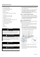
Site Preparation CAUTION Electrical Location: The electrical outlet should be located in the area marked “Electrical” in Figure 1*. The electrical outlet may also be located in a cabinet adjacent to the enclosure. However, an access hole would need to be created in the back left corner of the enclosure to route the power cord. Requirements: The electrical outlet must be on a dedicated non-GFI AC 110-120V, 60Hz, 15 amp circuit for each appliance and accept a three-prong grounding plug.
Panel Preparation (Panel-Ready Models) Panel Dimensions Prepare the Door Panel Description Width (1) Width (2) 18” single Column 17-1/2” (445 mm) 24” single Column 23-3/8” (594 mm) 30” single Column 29-3/8” (746 mm) 18” + 24” joined Columns 17-1/2” (445 mm) 23-1/2” (597 mm) 18” + 30” joined Columns 17-1/2” (445 mm) 29-3/8” (746 mm) 24” + 24” joined Columns 23-7/16” (595 mm) 23-7/16” (595 mm) 24” + 30” joined Columns 23-1/2” (597 mm) 29-3/8” (746 mm) 30” + 30” joined Columns 29-3/8” (
Panel Preparation (Panel-Ready Models) Panel Hole Mounting Positions 30” A* 29-3/8” (747 mm) B 24” 18” 23-3/8” (594 mm) 17-1/2” (445 mm) 13-1/2” (343 mm) 10-13/16” (275 mm) 7-7/8” (200 mm) * “A” dimensions are for a single appliance installation. See page 8 for panel widths for side-by-side appliance installations. Hole locations. Dimensions in ( ) are mm. A B B 4-3/8” (111) 1/2” (13) 6-1/2” (165) 1-5/16” (34) 1-5/16” (34) bluestarcooking.
Installation Instructions Tools and Materials • Mounting kit (included) • Before transporting the appliance, check access to the location where it will be installed (door size, maneuvering space in stairwells, etc). • Use a pallet-jack or appliance cart to move the appliance to the installation site before removing the appliance from the pallet. The appliance should always be transported in an upright position. If this is not possible, transport the appliance on its back.
Installation Instructions • Roll the appliance(s) into position near the kitchen enclosure, allowing enough space to work behind the appliance(s) for connecting the utilities and in the case of multiple appliances, the joining kit. Step 4 — Level the Appliance • Adjust the height of the rear wheels by turning the front adjusting bolts (1) clockwise (raise) or counterclockwise as required. Step 3 — Hook Up Electrical and Water • Unwind the power cord and connect it directly to the wall socket.
Installation Instructions If not installing appliances side-by-side, please skip to Step 7 on page 13. • Next join them at the front connecting each pair of plastic brackets (A) with the supplied rivets using a rivet tool. If a rivet tool is not readily available, an alternate method is to use a #4x.312 long (M3x8mm) bolt and nut to be supplied by the customer.
Installation Instructions Step 7 — Install Anti-Tipping Safety Brackets or Rear Wall Blocking WARNING To avoid danger of the appliance tipping over it is mandatory to secure the appliance to the wall by means of the two provided brackets, or if the brackets are not accessible, by means of a wood block at the rear wall of the enclosure.
Installation Instructions Step 9 — Install Panel (Panel-Ready Models) • Align the top center bracket on the panel with the recessed pocket in the door (6). Hook the panel brackets onto the shoulder bolts (7). 6 7 • Check the level of the appliance(s) and fit to surrounding cabinetry. If the kitchen enclosure is 84” (2134 mm) tall, the appliance(s) will need to be raised significantly.
Installation Instructions • Mark the wall where the holes are needed. • Reposition the bracket and secure it first to the appliance, then to the wall. In addition, it is required: • For a concrete block wall or 3/4” plywood wall, drill the wall with a 5/16” [8 mm] bit and insert the wall anchor. For a stud wall, drill a 1/8” (3 mm) pilot hole. bluestarcooking.com • The plastic connecting brackets must be screwed to the cabinets at all provided attachment points as described on page 16, Step 13.
Installation Instructions Step 12 — Adjust Panel (Panel-Ready Models) • The panel can be adjusted side-to-side at this point to obtain consistent gaps. Step 13 — Attach Appliance(s) to Surrounding Cabinetry • After leveling the appliance(s) and checking fit of the panel(s) or door(s) to surrounding cabinetry, secure the appliance to the adjacent cabinets by driving screws through the plastic connecting brackets. Screws should be provided by the customer. Keep the door open to ease access to the screws.
Installation Instructions Step 14 — Attach Door Handle Step 15 — Attach Venting Grille A BlueStar handle is provided with stainless door models, but must be ordered separately for panel-ready models. A forced air system assures ventilation through a grille positioned in the lower front part of the appliance. Each BlueStar Column comes with a 8-1/2” (216 mm) tall stainless steel grille. • The handle and nameplate kit is located in protective packaging taped to the back of the appliance.
Testing and Initial Startup Final Checklist Initial Startup • Check that the connection to the water system does not have any leaks and that the valve is easily accessible. Once the appliance is plugged in, the display will show the BlueStar logo, a brief info screen, then go dark. • Check that the electrical connection is correctly installed and that the circuit breaker is identified/marked for later use. • Check that the appliance is level and aligns with adjacent cabinets.
bluestarcooking.
(800) 449-8691