
manual

P/N 750323 Page 14
All specifications are subject to change without prior notification.
GAS CONNECTIONS
1. The installation of this appliance must
conform with all applicable local codes.
In the absence of local codes, the instal-
lation must conform to the latest level of
the National Fuel Gas Code, ANSI
Z223.1/NFPA 54. In Canada, the instal-
lation must be in accordance with the
current CAN/CGA B149.1 and B149.2.
2. This appliance can be configured to work
with either natural gas or LP gas. Verify
that the appliance and the incoming gas
supply are compatible. Check the rating
plate.
3. The gas supply line must be the same
size or larger than the gas inlet of the ap-
pliance. Your appliance has either a ½”
NPT or ¾” NPT gas inlet connection.
We recommend the supply line be ¼”
NPT larger than the gas inlet of the appli-
ance.
4. Sealant used on pipe joints must be resis-
tant to LP gas.
5. An installer provided manual shut-off
valve must be installed in the gas supply
line ahead of the appliance. This shut-off
must be easily accessible in case of emer-
gency.
6. All gas cooking equipment must have a
pressure regulator on the incoming ser-
vice line for safe and efficient operation.
This appliance is equipped with such a
gas pressure regulator. Incoming gas
pressure should be checked with a ma-
nometer. The correct manifold pressure
for natural gas is 5.0” wc. For LP gas the
correct manifold pressure is 10” wc.
7. Incoming line pressure upstream of the
appliance should be 1.0” wc greater than
the operating manifold pressure. Service
pressure may fluctuate for a variety of
reasons. Under no circumstances should
the factory installed regulator be re-
moved or by-passed.
8. The factory will include, but not
install a pressure regulator
This
regulator will withstand an input pressure
of ½ PSI (12” wc). If the incoming pres-
sure exceeds the maximum rating a step-
down regulator is required.
9. The appliance and its individual shut-off
valve must be disconnected from the gas
supply line during any pressure testing in
excess of ½ PSI [3.5 kPa].
10. The appliance must be disconnected from
the gas supply by closing its individual
shut-off during any pressure testing less
than ½ PSI [3.5 kPa].
11. Check to see that all installer supplied
pipes and fittings are clear of debris,
threading chips or other foreign particles
before connecting the appliance to the
supply line. Such particles will clog ori-
fices and/or valves when pressure is ap-
plied. Service to clean such clogs is not
covered by your warranty.
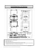
12. The incoming gas supply is brought from
the inlet pipe. This is the only connec-
tion required via the installer-supplied
shut-off valve.
13. If the appliance is to be installed with
flexible couplings and/or a “quick dis-
connect” the installer must use a com-
mercially approved AGA Design certi-
fied flexible connector at least ½” NPT
that complies with ANSI Z21.41. In
Canada the connector must comply with
CAN 16.10-88 and the “quick discon-
nect” device must comply with CAN
16.19M-79 and installed with a strain
relief device.
14. In Massachusetts, this appliance must be
installed with a 36” long flexible gas
connector
15. Before putting the appliance into service
test all gas connections for leaks. Use a
INSTALLATION