Designer Hoods Ventilation Hood Installation Instructions
TABLE OF CONTENTS Safety Instructions Safety Procedures 1 2 Wall Hood Installation Installation Instructions Wall Hood – 600 CFM In-Hood Fan (8” Round) Wall Hood – 600 CFM In-Hood Fan (8” Transition) Chimney & Island Hood – 600 CFM In-Hood Fan Wall Hood – 1200 CFM In-Hood Fan Chimney & Island Hood -1200 CFM In-Hood Fan 3 5 6 7 8 9 Island Hood Installation Installation Instructions Island Duct Cover Installation Island Duct Work Installation Remote Fan Installation 10 11 12 13 Metal Liner Installation
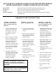
PLEASE READ COMPLETE INSTRUCTIONS BEFORE PROCEEDING. INSTALLATION MUST COMPLY WITH ALL LOCAL CODES. Save these instructions for the local electrical inspector’s use. Please leave these instructions with this unit for the owner. Please retain the instructions for future reference. Turn power circuit OFF at the service panel and lock panel door before wiring this unit.
SAFETY PROCEDURES FOR INSTALLING YOUR NEW PRIZER HOOD (continued) CAUTION – To reduce the risk of fire, electric shock, or injury to people, observe the following: CAUTION – For general ventilation use only. Do not use to exhaust hazardous or explosive materials or vapors. 1. Installation work and electrical wiring must be done by a qualified installer in accordance with all applicable codes and standards, including re-rated construction. 2.
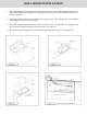
WALL HOOD INSTALLATION 1. The hood is shipped with the back panel and the transition. (Note: The transition is shipped upside down within the hood and can be flipped for rear discharge if desired. It must be removed then reinstalled – See Figures 1 though 3) 2. Detach the transition from the back panel removing four (4) screws. These shipping screws are needed for re-attaching the transition to the back panel. 3. Secure the transition to the top of the back panel, using the four (4) screws provided.
WALL HOOD INSTALLATION (continued) 1. Add 2” x 4” wood framing block to aid in securing the top and rear of the hood to the wall. (See Figure 6) 2. To mount CFM300, CFM600 and CFM1200 fans within hood walls. (See Figures 8, 9, 10 & 11) 3. Install the fan by aligning the fan holes with the PEM studs on the back panel. Tighten the fan to the panel using the hex nuts provided. (See Figures 8, 9, 10 & 11) 4. Connect the “Molex” from the fan to the “Molex” plug on the hood. (See Figure 4 from previous page) 5.
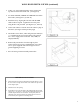
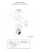
CFM 600 IN-HOOD FAN WALL APPLICATION – 8” ROUND COLLAR 7
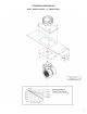
CFM 600 IN-HOOD FAN WALL APPLICATION – 8” TRANSITION 8
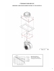
CFM 600 IN-HOOD FAN CHIMNEY AND ISLAND APPLICATION– 8” TRANSITION 9
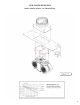
CFM 1200 IN-HOOD FAN WALL APPLICATION– 10” TRANSITION 10
CFM 1200 IN-HOOD FAN CHIMNEY AND ISLAND APPLICATION– 10” TRANSITION 10
ISLAND HOOD INSTALLATION INSTALLATION PREPARATION WARNING: To reduce the risk of fire, use only metal ductwork. 1. When installing a duct cover, the duct cover must be installed prior to the hood installation. See Figure 14 for duct cover installation instructions. 1. Decide the placement of the ductwork between the hood and the outside of the home. Your island hood has a top discharge which will run vertically. 2. Remove the baffle filters from hood shell. (See Figure 12) 2.
ISLAND DUCT COVER INSTALLATION 12
ISLAND HOOD DUCT WORK INSTALLATION 1. Cut a 10” diameter opening in the ceiling to accommodate the duct work necessary for proper ventilation. 2. Transfer the overall dimensions of the hood top plate onto the finished ceiling/unfinished surface. The top plate width and overall width will vary with the size of the hood. 3. Construct the frame using unistrut or wood 2x4’s. Due to the weight of the hood, structural support is necessary. (See Figure 3) 7.
REMOTE FAN ROOF MOUNT OR WALL MOUNT 14
15
METAL LINER INSTALLATION CHECK LOCATION • If your installation has been roughed-in (including ductwork and wiring), be certain there is nothing in the way of the mounting, pipes, other wiring etc. • If the installation has not been roughed in, check what is needed to create the framing and mounting hardware (all threads, nuts etc.). Be sure the location will not interfere with wiring, other utilities, or structural considerations.
TRANSITION INSTALLATION AND REMOVAL 1. The liner is shipped with the back-panel and the transition attached. 2. The transition is shipped upside-down in the liner and must be removed then, re-installed. 3. If an in-hood fan is furnished, the transition is shipped separately. 4. Detach the transition from the back-panel by removing four (4) screws. The shipping screws will be needed for re-installing the transition to the back-panel. 5.
INSTALLING METAL LINERS 1. If the “EZ Optional Trim Kit” will be used, it must be installed prior to mounting the metal liner to the hood shell. Use the provided #8 Phillips head screws. (See Figure 3) 2. Lift the metal liner into the hood shell. Due to the weight of the liner, 3 or 4 men may be required to hold the liner in place to insure a tight installation. 3. Install #6 x ½” screws through the pre-drilled “EZ Optional Trim Kit” mount holes through to the hood shell.
ELECTRICAL CONNECTIONS 1. Install three wires: black, white and green (#16 AWG) in ½” conduit from the service panel to the hood junction box. Power supply must be rated for 120v, 60 Hz, 15 amps (minimum). 2. Remove junction box and run power line through single hole and route to junction box mounted on back. 3. Connect black wire to power supplied black wire, white wire to power supplied white wire and green wire to ground supply green wire. 4.
COMPACT METAL LINER SLOPED SIDES (CMLSS) 23
METAL LINER SLOPED SIDES (MLSS) 24
PROFESSIONAL METAL LINER SLOPED SIDES (PMLSS) 25
METAL LINER FLAT SIDES (MLFS) 26
CHIMNEY HOOD INSTALLATION CHECK THE INSTALLATION LOCATION • If your installation has been roughed-in (including duct work and wiring), be certain there is nothing in the way of the mounting, pipes, other wiring etc. • If the installation has not been roughed-in, check what is needed to create the framing and mounting hardware (allthreads, nuts, etc.). Be sure the location will not interfere with wiring, other utilities, or structural considerations.
INSTALLING CHIMNEY STYLE HOODS 1. Position the Chimney Hood on its back and locate the transition inside the Chimney Hood; remove the (4) #8 x ½” self tapping screws at the top of the hood which hold the transition to the hood (save these screws for later use), separate the transition from the hood base and duct cover. 2. Install the transition to the duct work ensuring the bottom of the transition is centered and flush with the bottom of the duct cover.
INSTALLING CHIMNEY STYLE HOODS (continued) 8. Electrician may complete electrical connection to hood making the connection at the box inside the hood. (120 volt – See Figure 2) If using a remote fan please see section “Wiring remote Fan” 9. If using an in-hood CFM600 or CFM1200 fan, slide the fan mount over the studs at the junction of the hood and duct cover and use the 10 – 24 nuts supplied to attach the fan to the hood.
ALTERNATE INSTALLATION FOR A CHIMNEY STYLE HOOD In certain situations the installer may opt for a different installation sequence. The alternate sequence is listed below. 1. Drill holes in back of duct cover to align with structural members; fasten duct cover to wall using #10 x 2” self tapping screws; attach duct cover through ceiling opening in top of structure; if available. (See Figure 7) 2.
INSTALLING A CHIMNEY STYLE HOOD WITH A REAR DISCHARGE THROUGH DUCT COVER The Chimney Style Hood can adapt to a rear discharge application but with the following limitations: • A rear discharge application only works when using a 24” tall duct cover or taller. The 12” and 18” tall duct covers do not allow enough room to house the transition (with damper) and an elbow. The rear discharge cannot be made within the hood itself. It can only be made in the duct cover.
INSTALLING A CFM600 FAN IN A 30” WIDE CHIMNEY STYLE HOOD These instructions are only applicable when installing a CFM600 fan in a 30” wide chimney style hood. The Prizer 30” wide chimney style hood has an adapter plate installed inside the hood. In order to install a CFM600 fan within a 30” wide chimney style hood, first remove this adapter plate and use this plate in lieu of the plate shipped with the CFM600 fan. 1.
WIRING A REMOTE FAN When using a remote fan with a chimney style hood, follow the instructions noted below. NOTE: The chimney style hood is designed to accept a 3-speed fan motor only. It is not designed to accept a variable speed fan. 1. The Molex plug mounted within the front portion of the hood supplies power to the remote fan. 2. Connect the “male” Molex pigtail (included) with the remote fan to the Molex plug. 3. Route the wire ends into the hood’s “J-Box”. 4.
BAFFLE FILTERS, GREASE TROUGHS AND LIGHTS BAFFLE FILTERS Your baffle filters come with knobs to aid in filter placement and removal. Grab the knobs with your thumb and index finger. Simultaneously, slide and force the first baffle filter in an upward (slightly pitched) direction towards the ceiling. Spring clips have been attached within the framework to prevent the baffle filters from rattling when fan is operating. These spring clips will make it difficult to insert and remove baffle filters.
CLEANING RECOMMENDATIONS Brushed Stainless Steel, Hammered Stainless Steel, European Black Steel and Millennium Disk Stainless The Brushed Stainless Steel hood should be cleaned with microfiber cloths and stainless steel cleaner. Always wipe in a manner which follows the grain. DO NOT clean with paper towels as they will scratch the surface. Cleaning cloths other than microfiber may scratch the surface of the hood.
TROUBLESHOOTING TIPS PROBLEM OR CONDITION POSSIBLE SOLUTION Fans and lights do not operate • A fuse may be blown or the circuit breaker tripped. Replace the fuse or reset the breaker. • Electrical connections at the wiring box may have been made incorrectly. Contact the installer. Fan runs but lights do not operate • The bulb may have burned out. • Switch operation may be faulty. Fan runs but lights do not operate • Connect fan directly to a supply cord, by passing hood control.