
Operation Manual
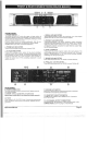
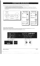
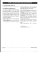

FRONT
&
REAR CONNECTIONS
(MA500-MA800)
r
portion
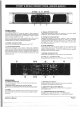
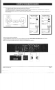
FRONT
PANEL
1.
POWER
SWITCH
To
turn
the
unit
ON
or
OFF,
press
the
uppei
this
button.
Before turning
on the
amplifier,
c
(Caution: Always turn
on
your power amplifier
last,
after
all
yoi
other
connected equipment,
and
always
turn
off
your power
2.
POWER
LED
INDICATORS
These
LEDs illuminate when
the
power
is
turned
"ON".
LEDs
illuminate
if any
section
of the
power amplifier's
ithin
3dB
of
clipping.
Occasional
blinking
of the
LEDs
The
output
gre
acceptable,
but if
they
should
turn
down
either
the
power
audible
distortion.
rmittently
you
4.
SIGNAL
LED
INDICATORS
greater than
100
mV
at
that
criann
of
the
nplifier
5.
PROTECT
LED
INDICATORS
These LEDs illuminate
if the
power amplifier's output connection
is
shorted
,
the
load impedance
is
too
low.
Or if
there
is an
internal
malfunction
When either
of
these
LEDs
is
lit
up,
turn
OFF
the
power
and
check
the
output's
connection
to
verify
that
it
is
correct,
then
turn
ON the
power again.
6.
LEVEL
CONTROLS
These
control
the
level
of
signal
coming
into
each
channel.
The
actual
voltage attenuation
of the
amplifier
is
shown
in
dB.
Turn these
controls
counterclockwise
if the
Limit
LEDs illuminate steadily
8.
PARALLEL
LED
INDICATORS
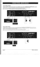
REAR
PANEL
9.
POWER
CONNECTOR
The
cord connector
is
used
to
connect
the AC
power source
to
your
power
amplifier.
(
CAUTION
:
Always
operate
the
unit
with
the AC
ground
wire
connected
to the
electrical
system
ground)
10.
FUSE
Fuse holders
for
5A-15A/250V
fuses.
If
these fuses
continuous!)
blow,
shutofftheunitand
have
itserviced
by
qualified
service
11.GROUND
LIFT
SWITCH
Switch
up to
disconnect
the
chassis from ground
if
necessary
to
eliminate
hum
caused
by
ground
loops.
12.
SENSITIVITY SELECTOR SWITCH
The MA
Series
amplifiers
offer
3
SENSITIVITY
of
operation:
0.7V
1.0V
&
1.44V.
13.
COMPRESSOR SELECTOR SWITCH
The
MA
Series amplifiers offer
OFF or
COMPRESSOR.
The
compressor only
works
when
the
1
v
sensitivity
is
selected.
Reference
Manual
Page
9