DC UPS EN User Manual Page 1
Table of Contents EN 1. Introduction…………………………………………………………3-4 1.1 General Introduction ……………………………………….………3 1.2 Panel Introduction …………………………………………….……3 1.3 The 7 Pin Terminal Connecters Introduction Table …………….4 2. Safety Information……………………………………………………5 3. Package Contents……………………………………………………6 4. Installation …………………………………………………………7-9 4.1 Wire Connection …………………………………………………7-8 4.2 Wall-Mounting Instructions (Optional) ……………………………9 5. Operation…………………………………………………….………10 6.
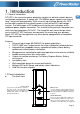
1. Introduction 1.1 General Introduction DC UPS is the innovative power protection solution for delicate network devices and telecom equipments. It equips with 12V/30Watts power capacity and internal long 7 amp-hour backup battery. With universal input voltage design, this UPS can be widely applied to the majority power system without AC input voltage transfer. The advantages of DC output are saving the cost and space of the additional power adapter connection.
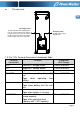
The rear view EN DC output socket TheDC outputincludes12VDCpower, four dry contact signals and common return point for these signals. Please findthe definensand wire connections for DC output socket as below table. AC input socket TheAC input socket is IEC320 C14. 1.
2. Safety Information EN Internal battery voltage is 12V DC. Incorrect battery connection or replacement creates risk of explosion. Use only vender approved replacement batteries. The DC UPS is intended for installation and operation in a controlled environment (temperature controlled, indoor area free of conductive contaminants). Refer to specifications in this manual. No user-serviceable parts exist inside the unit. Refer repair issues only to qualified personnel.
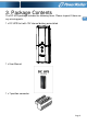
3. Package Contents The DC UPS package includes the following items. Please inspect if there are any missing parts.
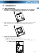
4. Installation EN 4.1 Wire Connection 1. Remove the wire connection cover in the rear of the DC UPS. Keep the cover will and reinstall the cover after all the wires are well-connected. 2. Plug IEC-LOCAL power cord into the AC input socket on the back of DC UPS. Do not connect the AC power cord to utility outlet prior to this process. 3. Connect DC UPS to network device. 3.
3.2 If the telemetry cable is not enclosed: (1) Cut and strip the self-prepared cable leads, and then attach the leads to the 7-position connector. Make sure that the correct wire gauges are used for the safety (Please refer to “1.3 The 7 Pin Terminal Connecter Intro Table”) (2) Plug the 7-conductor cable into the outlet of the DC UPS (3)Then place the cable between the two sticks for fixing the cable as the following picture 4. Close the wire connection cover 5.
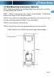
4.2 Wall-Mounting Instructions (Optional) NOTE: Required hardware not included. Refer to the wall-mount instructions for required tools and materials. STEP 1: Make a mark on the wall in the 2 screw locations. The distance between the centers of the 2 screws are 80cm. STEP 2: Use a drill to drill holes where you made the mark on the wall. If you drill into a wall stud, proceed to Step 5. If not, go to Step 4. STEP 3: Insert anchor(s) into the hole(s).
5. Operation After the installation, you can start to operate the DC UPS and let your device running under uninterruptible power supply environment as the following procedure. STEP 1: Plug the AC input power cord of the DC UPS into the wall outlet (The utility power outlet) STEP 2: Push the power on/off switch and you may hear a long beep buzzer alarm for knowing the unit is properly turned on. You may turn the audible alarm off by pushing the mute switch button to ON (Push down) position.
6. Available & Visual Alarms Front-Panel Label ON A/C Visual Indicator Audible Alarm None Green LED lights Testing Battery Green LED flashes None ON Battery Yellow LED lights Tone every 5 seconds EN Description The DC UPS is operating on A/C The DC UPS is conducting a self-test. This automatic procedure is normal and will occur when the unit is switched on, and periodically thereafter. This procedure will last approximately 5 minutes. The DC UPS is operating on battery power.
7. Battery Replacement Procedure The DC UPS is designed with an easy-access battery cover. STEP 1 Turn off power switch. Disconnect the DC UPS from power and any connected devices. Remove the battery door on the front of the DC UPS by pulling up the battery door. STEP 2 Remove the battery from enclosure; remove the wire connections from the battery.
8. Specifications Model Name DC UPS Nominal input voltage INPUT OUTPUT 80~260Vac Acceptable Input frequency Range 45Hz~65Hz Normal Voltage Output Voltage Range Line Mode Efficiency Type/Rating BATTERY 30W 12Vdc 10.5V~13.8V > 80% 12V/7Ah x 1pc Discharge Prevention 10.5V ± 0.
MUTE FUNCTION OPERATING ENVIRONMENT Switch on Buzzer disable Switch off Buzzer enable Operating temperature 0℃ to 40℃ Operating humidity 0% to 90% Operating Elevation 0 to 3000m Weight PHYSICAL Dimension (W x H x D) EN 3.5 kgs 120mm(W) x 358mm(H) x 86.