USER MANUAL On-Line UPS 1000VA/1500VA/2000VA/3000VA Uninterruptible Power Supply System
CONTENT USER MANUAL .......................................................................................1 1. Safety and EMC Instructions ............................................................1 1.1 Installation ..........................................................................................1 1.2 Operation ............................................................................................9 1.3 Maintenance, servicing and faults ....................................................
EN 9.1 Operation ..........................................................................................32 9.2 Storage .............................................................................................32 9.3 Battery Replace ................................................................................32 10. Technical Data ................................................................................33 10.1 Electrical specifications .........................................................
1. Safety and EMC Instructions EN SAVE THESE INSTRUCTIONS – This manual contains important instructions for models PowerWalker VFI 1000/1500/2000/3000RT LCD that should be followed during installation and maintenance of the UPS and batteries. Please read carefully the following user manual and the safety instructions before installing the unit or using the unit! 1.
• Do not open or mutilate the battery or batteries. Released electrolyte is harmful to the skin and eyes. It may be toxic. • Icon Φ on the rating label stands for phase symbol. • A battery can present a risk of electrical shock and high short circuit current. • Remove watches, rings, or other metal objects from the hand. • Use tools with insulated handles.
standing water or running water. o Any area with extraordinarily high or low temperature (above 40˚C or below 0˚C) and humidity of more than 90%. EN o Any area exposed to direct sunshine or near any heating apparatus. (Maximum ambient temperature rating is 40°C.) • o Any area with serious vibrations. o Outdoor. In the event that there is fire occurring in the vicinity, please use dry-power extinguishers. The use of liquid extinguishers may give rise to the danger of electric shock. ★ 1.1.
3. Pull out the LCD box and rotate it in a clockwise direction to 90 degree and then push it back in the front panel.
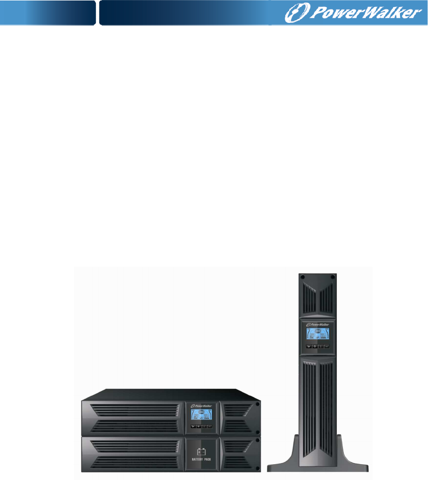
Rack-mount setup EN The series can be installed in 19 inches racks. Both the UPS and external battery enclosure need 2U of rack space. Use the following procedure to install UPS in a rack. 1. Align the mounting ears with screw holes on the side of the UPS, and tighten the screw. 2. Assemble the rack rails with the rack-mounting. 3. Slide in the UPS into the rack rail and lock it in the Rack-mounting. 4. Tighten the screw, and then the load can be connected. 1.1.
on side of the front panel to allow the outlet wire of the EBM to pass through the gate and then reassemble front panel.
Connecting the EBM in a rack form EN 1. Using the same method as assembling UPS in a rack form, assemble EBM into the rack-mounting on the top or bottom of the UPS. 2. Connect the earth line from UPS (port A ) to EBM (port B ) 3. Take off the LCD box, and unscrew the internal screws. 4. Take off the front panel, and connect the battery terminal (A) from UPS to EBM terminal (B) shown as below.
Connecting multiple EBMs in Tower form 1. Connect Earth line between UPS and the first EBM, and then connect Earth Line between the first EBM and the second EBM. 2. Take off the front panel, and connect the battery terminal (A) from UPS to EBM terminal (B) shown as below. And then connect the battery terminal (D) from the first EBM to the battery terminal (E) from the second EBM.
EN E B D A C Note: Three or more EBMs can be connected to the UPS in the same way as shown above. Note: After connect the EBMs, please do not forget to set the number of EBMs on LCD, please refer to chapter 7 “Setting by LCD module” for setting method. If use the nonstandard EBMs, please call local dealer or distributor for setting method. 1.
★ Use No. 12 AWG (for 3KS input wire), 90°C copper wire and 4.4 lb-in Torque force when connecting to terminal block. ★ Use No. 10AWG (for all models battery wire), 90°C copper wire and Anderson PP45 connectors for user’s external battery cabinet. 1.3 Maintenance, servicing and faults ★ The UPS operates with hazardous voltages. Repairs may be carried out only by qualified maintenance personnel. ★ Caution - risk of electric shock.
1.3.1 UPS and Battery Care EN For the best preventive maintenance, keep the area around the UPS clean and dust-free. If the atmosphere is very dusty, clean the outside of the system with a vacuum cleaner. For long battery life, keep the UPS at an ambient temperature of 25°C (77°F) 1.3.2 Storing the UPS and Batteries When the UPS is intended to store for a long period, recharge the battery every 6 months by connecting the UPS to utility power. The batteries charge to 90% capacity in approximately 4 hours.
Note: If you are not qualified service personnel to replace the battery, do not attempt to open the battery cabin. Please call local dealer or distributor immediately. EN 1.3.4 Replacing UPS Internal Batteries Follow the steps and Charts as below to replace batteries: 1. Take off the LCD box, and remove the screws. 2. Slide and Pull the front panel leftward and then take it off. 3. Disconnect the cable from the UPS and battery pack. 4. Remove the right inner battery bracket. 5.
1.3.5 Testing New Batteries EN For a battery test, please check: The batteries must be fully charged. The UPS must be in Normal mode with no active alarms. Don’t take on/off the load. To test batteries: 1. Connect the UPS to utility power for at least 48 hours to charge the batteries. 2. Press and hold the “I” button 1 second to start the battery test on line mode or HE mode. The status display string shows “TEST” 1.3.6 Recycling the Used Battery: Warning: Never dispose the batteries in a fire.
1.6 Standards * Safety IEC/EN 62040-1-1 EN * EMI Conducted Emission..........................:IEC/EN 62040-2 Category C1 Radiated Emission.............................:IEC/EN 62040-2 Category C1 Harmonic Current...............................:IEC/EN 61000-3-2 Voltage Fluctuation and Flicker..........:IEC/EN 61000-3-3 *EMS ESD...................................................:IEC/EN 61000-4-2 Level 3 RS.....................................................:IEC/EN 61000-4-3 Level 3 EFT..............
2. Description of Commonly Used Symbols EN Some or all of the following symbols may be used in this manual.
3. Introduction This On-Line-Series is an uninterruptible power supply incorporating double-converter technology. It provides perfect protection specifically for Novell, Windows NT and UNIX servers. The double-converter principle eliminates all mains power disturbances. A rectifier converts the alternating current from the socket outlet to direct current. This direct current charges the batteries and powers the inverter.
4. Panel Description EN LCD Screen ON Button/ OFF-Button Alarm Silence Select-Button Enter-Button The Display Panel Switch ON-Button Function Turn on UPS system: By pressing the ON-Button “I” the UPS system is turned on. Deactivate acoustic alarm: By pressing this Button an acoustic alarm can be deactivated in the battery mode. By short touch this Button all acoustic alarms can be deactivated in all mode.
EN The LCD Display Display Function Input Information Display Function Output Information It indicates input voltage/frequency value, which are displayed alternately. It indicates output voltage/frequency value, which are displayed alternately. It indicates the input is connected with mains, and the input power is supplied from the mains. It indicates the Output plug. It indicates the Number of the input supplied from the mains. It indicates the Number of the output connected with load.
5. Connection and Operation EN The system may be installed and wired only by qualified electricians in accordance with applicable safety regulations! When installing the electrical wiring, please note the nominal amperage of your incoming feeder. 5.1 Inspection Inspect the packaging carton and its contents for damage. Please inform the transport agency immediately should you find signs of damage. Please keep the packaging in a safe place for future use.
(2) UPS Output Connection The output of the UPS is IEC socket-types. Simply plug the load power cord to the output sockets to complete connection. Use one cord for every 5A load. Model No. 1K(S)/1.5K(S)/ 2K(S) 3K(S) Output Socket (pcs) 8 * IEC320 C13 8 * IEC320 C13 + 1 * C19 The wiring configuration is shown as the following procedure: a) Remove the small cover of the terminal block 2 b) Use 2.
NC EN Normally the EPO connector is closed with a wire on the rear panel. Once the connector is open, the UPS would stop the output until the EPO status is disabled. Enable the EPO status Disable the EPO status 5.3 Battery charge Fully charge the batteries of the UPS system by leaving the UPS system connected to the mains for 1-2 hours. You may use the UPS system directly without charging it but the stored energy time may be shorter than the nominal value specified. 5.
change within 30 seconds; in resting mode, UPS will detect the change within 3 minutes; (2) Manual test Test the function of the UPS system by pressing the On-Switch “I” for more than 1 second, the UPS would detect whether the battery is connected or the battery is low immediately. Also the UPS could do the test automatically and periodically, the period time could be set by user, the default value is 7 days. 5.
(3) The battery connection procedure is very important. Any incompliance may result in the risk of electric shock. Therefore, the following steps must be strictly complied with. EN (4) Make sure the mains input is cut off, if there is a battery breaker then turn it off first. (5) Remove front panel, connect the battery via Anderson PP45 connectors. Prepare the battery cable which should be able to carry the current of >50A for all models, the cross section area should be 2 great than 4 mm for all model.
6. Operating Mode for All Models The different string could be displayed on the LCD screen corresponding to their own operating modes, and they are illustrated as the following table. At any time, only one normal operating string or fault string is presented. But the warning, even several warnings could appear in a certain normal operating mode at one time. And the normal operating mode string and the warning string would be shown circularly.
EN Note: Please follow the following steps to connect the generator: ● Activate the generator and wait until the operation is stable before supplying power of the generator to the UPS (be sure that the UPS is in idle mode). Then turn on the UPS according to the start-up procedure. After the UPS is turned on, then the loads can be connected to the UPS one by one. ● The power capacity of the AC generator should be at least twice of the UPS capacity. 6.
The UPS does not have the backup function when it is in bypass mode. The power used by the load is supplied from the utility power via internal filter. 6.4 NO output mode EN The LCD display in No output mode is shown in the following diagram. The information about the utility power, the battery level, the UPS output and the load level could be displayed. The “STbY” string indicates the UPS is working in the No output mode. ■ The No output mode 6.
6.7 Converter mode EN In converter mode, on LCD display, the mode string is “CVCF”. The UPS would free run with fixed output frequency (50Hz or 60Hz) in converter mode. Once the mains is loss or abnormal, the UPS would transfer to battery mode and the load is supplied continuously by the battery. 1) It could be enabled through the LCD setting or the software (Winpower, etc.). 2) The load should be derating to 70% in converter mode. 6.8 Abnormal mode In abnormal mode such as Bus fault etc.
7. Setting by LCD Module The output voltage, frequency, Bypass status and operating mode in No output mode or Bypass mode, Two Load segments in output mode, The number of EBM in all mode could be set directly through LCD module. The output voltage could be set to 208V, 220V, 230V and 240V. The output frequency could be set to 50Hz and 60Hz. The bypass state could be set to enable and disable. The operating mode of UPS could be set between the Line mode, ECO mode and Converter mode.
EN “Bypass Enable” is selected, and turn to no output mode in several seconds after “Bypass Disable” is selected; Operating mode could be selected in “UPS”, “ECO”, “CVF”(Here “UPS” means the normal inverter mode, “ECO” means the high efficiency mode, and “CVF” means the converter mode), The mode change would be active only after the UPS is turned on; The number of EBM could be selected in “000” to “009”(Here “000” means no EBM connected).
8. Trouble Shooting If the UPS system does not operate correctly, check the operating status on the LCD display.
EN Battery low Battery voltage is low Charge fail Inverter temperature high Ambient temperature high Battery open The charge is broken Inside temperature of the UPS is too high The ambient temperature is too high Battery pack is not connected correctly Battery fault Battery may need to be replaced Overload Overload Site fail EPO active Bus fault(Low/high/ Unbalance/soft start) Inverter fault(Low/high/soft start) Over temperature fault Phase and neutral conductor at input of UPS system are reversed
9. Maintenance 9.1 Operation The UPS system contains no user-serviceable parts. If the battery service life (3~5 years at 25°C ambient temperature) has been ex ceeded, the batteries must be replaced. In this case please contact your dealer. 9.2 Storage If the batteries are stored in temperate climatic zones, they should be charged every three months for 1~2 hours. You should shorten the charging intervals to two months at locations subject to high temperatures. 9.
10. Technical Data 10.1 Electrical specifications EN INPUT Model No. 1K(S) 1.5K(S) 2K(S) Phase 1 Frequency (45~55)/(54~66) Hz Max Current(A) 7.5 10.5 3K(S) 13.5 20 OUTPUT Model No. 1K(S) 1.5K(S) 2K(S) 3K(S) Power rating 1kVA/0.9kW 1.5k/1.35kW 2kVA/1.8kW 3kVA/2.7kW Voltage 208/220/230/240×(1 士 1%)VAC Frequency 50/60(±0.2)Hz (Battery mode) Wave form sinusoidal BATTERIES Model No. 1K 1.5K 2K 3K Number and type 3×12V 7Ah 4×12V 7Ah 4×12V 9Ah 6×12V 9Ah 10.
10.4 Dimensions and weights Model Net weight (kg) UPS Case Dimension (mm) (W x H x D) EBM Case 34 1000 1000S 1500 1500S 2000 2000S 3000 16.2 8.4 19.7 9.3 19.7 438X86.5x436 Dimension (mm) (W x H x D) 9.3 28.6 3000S 13.2 438X86.5x608 Net weight (kg) 22.2 27.5 40.
11. Communication Port 11.1 RS-232 and USB communication ports EN To establish communication between the UPS and a computer, connect a computer to one of the UPS communication ports by using an applicable communication cable. NOTE: Only one of the communication ports can be active at one time. The USB port has priority over the RS-232 port. When a communication cable is installed, the power management software can exchange data with the UPS.
11.3 USB port The UPS can communicate with a USB-compliant computer by using HID-compatible power management software. To establish communication between the UPS and a computer, connect the USB cable that comes with the UPS to the USB port on the UPS. Connect the other end of the USB cable to the USB port on a computer. 11.4 Installing a Serial Network Management Card (optional) Each UPS has one available communication bay, which supports the optional Serial Network Management Card.
The following figures show schematic of the dry out/in contacts. EN Dry out contact schematic Dry in contact schematic The following table shows the options for the dry out/in contacts Dry out signal Description Summary Alarm Activated when any warning happens On Battery Activated when the UPS operates on battery Battery Low Activated with the “bLOW” alarm UPS ok Activated when the UPS has no alarms and no fault. On Bypass Activated when the UPS has bypass output.
12. Software Installation WinPower is UPS monitoring software, featuring user-friendly interface to monitor and control your UPS. This unique software provides complete power protection for computer system while power failure. With the software users can monitor any UPS status on the same LAN.
Appendix: Rear panel The UPS rear panel description table and pictures are shown as below: EN No.
EN USB AC INPUT ~ LS1 AC OUTPUT 250V 10A INTELLIGENT SLOT RS232 250V 10A LS2 AC OUTPUT ~ EPO ~ 250V 16A DRY IN DRY OUT USB ~ LS1 AC OUTPUT 250V 10A INTELLIGENT SLOT EPO RS232 250V ~10A USECOPPER CONDUCTOR ONLY.FOR SUPPLY CONNECTIONS, USEWIRESSUITABLE FORATLEAST 75℃.