Online UPS PowerWalker VFI 6000 LCD (Tower & Rack) PowerWalker VFI 10000 LCD (Tower & Rack) Manual EN/ES EN
EN Please comply with all warnings and operating instructions in this manual strictly. Save this manual properly and read carefully the following instructions before installing the unit. Do not operate this unit before reading through all safety information and operating instructions carefully.
Table of Contents 1. IMPORTANT SAFETY INSTRUCTION ............................................................................................. 3 2. INSTALLATION AND OPERATION.................................................................................................. 5 2-1. UNPACKING AND INSPECTION .............................................................................................................................................. 5 2-2. REAR PANEL VIEW ........................................
1. IMPORTANT SAFETY INSTRUCTION SAVE THESE INSTRUCTIONS – This manual contains important instructions for models PowerWalker VFI 6000/1000 LCD that should be followed during installation and maintenance of the UPS and batteries. EN This product is specially designed for PCs and it is not recommended for use in any life-supporting system and other specific important equipment. This equipment can be operated by any individual with no previous training.
Do not keep or use this product in any of the following environments: o Any area with combustible gas, corrosive substance or heavy dust. o Any area with extraordinarily high or low temperature (above 40˚C or below 0˚C) and humidity of more than 90%. o Any area exposed to direct sunshine or near any heating apparatus. o Any area with serious vibrations. o Outdoor. In the event that there is fire occurring in the vicinity, please use dry-power extinguishers.
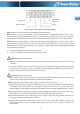
2. Installation and Operation EN There are two different types of online UPS: standard and long-run models. Please refer to the following model table. Model Type Model Type 6000 6000L 10000 10000L Standard Long-run model model 6000R 6000RL 10000R 10000RL We also offer optional parallel function for these two types by request. The UPS with parallel function is called as “Parallel model”. We have described detailed installation and operation of Parallel Model in the following chapter. 2-1.
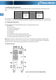
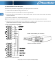
EN Diagram 2: Input/Output Terminal Diagram 3: Rear Panel Overlook 6000R(L)/10000R(L) Diagram 4: Input/Output Terminal Diagram 5: 6KR/10KR battery pack rear panel 1. RS-232 communication port 2. USB communication port 3. Emergency power off function connector (EPO connector) 4. Share current port (only available for parallel model) 5. Parallel port (only available for parallel model) 6. Intelligent slot 7. Cooling fan 8. External maintenance bypass switch port 9. Maintenance bypass switch 10.
2-3. Single UPS Installation Installation and wiring must be performed in accordance with the local electric laws/regulations and execute the following instructions by professional personnel. EN 1) Make sure the mains wire and breakers in the building are enough for the rated capacity of UPS to avoid the hazards of electric shock or fire. NOTE: Do not use the wall receptacle as the input power source for the UPS, as its rated current is less than the UPS’s maximum input current.
Input Neutral Output Line Input Line Output Neutral Ground Terminal Block wiring diagram for 6000R(L)/10000R(L) NOTE 1: Make sure that the wires are connected tightly with the terminals. NOTE 2: There are two kinds of outputs: output terminal/outlets and programmable terminal. Please connect non-critical devices to the programmable terminal and critical devices to the output terminal/outlets.
2-4. UPS Installation for Parallel System If the UPS is only available for single operation, you may skip this section to the next. 1) Install and wires the UPSs according to the section 2-3. 2) Connect the output wires of each UPS to an external output breaker. EN 3) Connect all external output breakers to a major output breaker. Then this major output breaker will directly connect to the loads. 4) Each UPS is connected to an independent battery pack.
Parallel communication port connection EN Diagram 4 Share current cable connection Diagram 2: Power cable connection Wiring diagram of parallel system for 6000R(L)/10000R(L) 2-5. Software Installation For optimal computer system protection, install UPS monitoring software to fully configure UPS shutdown. You may insert provided CD into CD-ROM to install the monitoring software. If not, please follow steps below to download and install monitoring software from the internet: 1.
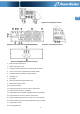
3. Operations 3-1. Button Operation Button Function EN ON/Enter Button Turn on the UPS: Press and hold the button more than 0.5s to turn on the UPS. Enter Key: Press this button to confirm the selection in setting menu. OFF/ESC Button Turn off the UPS: Press and hold the button more than 0.5s to turn off the UPS. Esc key: Press this button to return to last menu in setting menu. Test/Up Button Mute/Down Button Test/Up + Mute/Down Button Battery test: Press and hold the button more than 0.
LCD Panel: EN Display Function Backup time information Indicates the backup time in pie chart. Indicates the backup time in numbers. H: hours, M: minutes, S: seconds Fault information Indicates that the warning and fault occurs. Indicates the fault codes, and the codes are listed in details in section 3-9. Mute operation Indicates that the UPS alarm is disabled. Output & Battery voltage information Indicates the output voltage, frequency or battery voltage.
Indicates the bypass circuit is working. Indicates the ECO mode is enabled. Indicates the Inversor circuit is working. Indicates the output is working. EN Battery information Indicates the Battery capacity by 0-25%, 26-50%, 51-75%, and 76-100%. Indicates the battery is fault. Indicates low battery level and low battery voltage. Input & Battery voltage information Indicates the input voltage or frequency or battery voltage. Vac: Input voltage, Vdc: battery voltage, Hz: input frequency 3-3.
CPU communication failure Overload 3-4. Single UPS Operation 1. Turn on the UPS with utility power supply (in AC mode) 1) After power supply is connected correctly, set the breaker of the battery pack at “ON” position (the step only available for long-run model). When setting input breaker at “ON” position, the fan will start running. Then, set the internal output breaker at “ON” position. The UPS will supply power to the loads via the bypass. Now, the UPS is operating in Bypass mode.
5. Battery mode operation EN 1) When the UPS is in Battery mode, the buzzer will beep according to different battery capacity. If the battery capacity is more than 25%, the buzzer will beep once every 4 seconds; If the battery voltage drops to the alarm level, the buzzer will beep quickly (once every sec) to remind users that the battery is at low level and the UPS will shut down automatically soon.
2) Some warning alarms can’t be muted unless the error is fixed. Please refer to section 3-3 for the details. 10. Operation in warning status 1) When Fault LED flashes and the buzzer beeps once every second, it means that there are some problems for UPS operation. Users can get the fault code from LCD panel. Please check the trouble shooting table in chapter 4 for details. 2) Some warning alarms can’t be muted unless the error is fixed. Please refer to section 3-3 for the details. 11.
EN 4) Turn on the input breakers and internal output breakers of all UPSs in the parallel systems, and turn on each UPS in turns. Make sure that AC mode LED or Battery mode LED displays in each UPS. Measure the output voltage of each UPS to check if the voltage difference is less than 2V (typical 1V) with multimeter. If the difference is more than 2V, please check that parallel cable or share current cable are connected well. If they are all connected well, maybe it’s UPS internal issue.
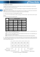
ADD Add ON On OFF Off FBD Not allowed OPN Allow RES Reserved EN 3-7. LCD Setting There are three parameters to set up the UPS. Refer to following diagram. Parameter 1: It’s for program alternatives. There are 15 programs to set up. Refer to below table. Parameter 1 Parameter 2 and parameter 3 are the setting options or values for each program.
01: Output voltage Interface EN 02: Output frequency Interface 60 Hz, CVCF mode 50 Hz, Normal mode ATO 03: Voltage range for bypass Interface 04: Frequency range for bypass Interface Setting Parameter 3: Output voltage You may choose the following output voltage in parameter 3: 208: Presents output voltage is 208Vac 220: Presents output voltage is 220Vac 230: Presents output voltage is 230Vac 240: Presents output voltage is 240Vac Setting Parameter 2: Output Frequency Setting the output frequ
05: ECO mode enable/disable Interface 06: Voltage range for ECO mode Interface 07: Frequency range for ECO mode Interface Setting Parameter 2: Low voltage point in ECO mode. The setting range is from 5% to 10% of the nominal voltage. Parameter 3: High voltage point in ECO mode. The setting range is from 5% to 10% of the nominal voltage. Setting Parameter 2: Set low frequency point for ECO mode. 50 Hz system: Setting range is from 46.0Hz to 48.0Hz. 60 Hz system: Setting range is from 56.
10: Programmable output setting Note:This function is not supported by 6000R(L)/10000R(L) model. Interface EN Setting Parameter 3: Set programmable output. You may choose the following three options: ON: Programmable output is manually switched on timelessly. OFF: Programmable output is manually switched off. However, if UPS restarts, this setting will automatically go to “ATO” status. ATO: Programmable output is automatically turned on or cut off according to battery or load status.
13: Battery voltage adjustment Interface Setting Parameter 2: Select “Add” or “Sub” function to adjust battery voltage to real figure. Parameter 3: the voltage range is from 0V to 5.7V, the default value is 0V. 14: Charger voltage adjustment Interface Setting Parameter 2: you may choose Add or Sub to adjust charger voltage Parameter 3: the voltage range is from 0V to 9.9V, the default value is 0V.
CVCF mode Description When input frequency is within 46 to 64Hz, the UPS can be set at a constant output frequency, 50 Hz or 60 Hz. The UPS will still charge battery under this mode. LCD display EN Battery mode Description When the input voltage is beyond the acceptable range or power failure, UPS will backup power from battery and alarm will beep every 4 seconds.
3-9.
4. Trouble Shooting EN If the UPS system does not operate correctly, please solve the problem by using the table below. Symptom Possible cause Remedy No indication and alarm in the front The AC input power is not Check if input cable firmly display panel even though the mains is connected well. connected to the mains. normal. The icon and the warning code flash on LCD display and alarm beeps every second. The icon and flash on LCD display and alarm beeps every second.
5. Storage and Maintenance 5-1. Storage Before storing, charge the UPS at least 7 hours. Store the UPS covered and upright in a cool, dry location. During storage, recharge the battery in accordance with the following table: Storage Temperature Recharge Frequency Charging Duration -25°C - 40°C Every 3 months 1-2 hours 40°C - 45°C Every 2 months 1-2 hours 5-2. Maintenance The UPS system operates with hazardous voltages. Repairs may be carried out only by qualified maintenance personnel.
6. Specifications MODEL CAPACITY* INPUT EN Voltage Range 6000 6000R 6000 VA / 4800 W Low Line Loss Low Line Comeback High Line Loss High Line Comeback 110 VAC ± 3 % at 50% Load; 176 VAC ± 3 % at 100% Load Low Line Loss Voltage + 10V 300 VAC ± 3 % High Line Loss Voltage - 10V 46Hz ~ 54 Hz @ 50Hz system 56Hz ~ 64 Hz @ 60Hz system Single phase with ground ≧ 0.
Online UPS PowerWalker VFI 6000 LCD (Tower & Rack) PowerWalker VFI 10000 LCD (Tower & Rack) Manual EN/ES ES
ES Siga estrictamente todas las advertencias e instrucciones de este manual. Guarde este manual antes de instalar la unidad UPS para leer todas las instrucciones atentamente. No utilice el SAI antes de leer atentamente toda la información de seguridad y las instrucciones de uso.
Índice 1. INSTRUCCIONES IMPORTANTES DE SEGURIDAD .......................................................................... 3 2. INSTALACIÓ N Y OPERACIÓ N ....................................................................................................... 5 2-1. DESEMBALAJE E INSPECCIÓ N ............................................................................................................................................... 5 2-2. VISTA DEL PANEL POSTERIOR ...........................................
1. INSTRUCCIONES IMPORTANTES DE SEGURIDAD GUARDE ESTAS INSTRUCCIONES – Este manual contiene instrucciones importantes relativas a las LCD de los modelos PowerWalker VFI 6000/1000 LCD, que deben seguirse durante la instalación y en las operaciones de mantenimiento del SAI y de las baterías. ES Este producto ha sido diseñado especialmente para ordenadores personales y no está diseñado para equipos de soporte vital u otros equipos importantes.
No almacene u opere el producto en los siguientes entornos: o Lugares con gases inflamables, sustancias corrosivas o mucho polvo. o Cualquier lugar extremadamente cálido o frío (por encima de los 40 °C o por debajo de los 0 °C) o con una humedad relativa superior al 90%. o Cualquier lugar expuesto a la luz solar directa o cerca de equipos que emitan calor. o Cualquier lugar expuesto a fuertes vibraciones. o Exteriores.
2. Instalación y Operación ES Existen dos tipos de SAI on-line: modelo estándar y modelo de larga autonomía. Por favor refiérase al modelo en la siguiente tabla. Modelo Tipo Modelo Tipo 6000 6000L 10000 10000L Modelo Modelo Standard Larga autonomía 6000R 6000RL 10000R 10000RL De manera opcional puede solicitar la “función paralelo” en ambos modelos. La instalación y operación del SAI en “modo paralelo”, se describe en detalle en el capítulo siguiente. 2-1.
ES Figura 2: Terminales entrada/salida Figura 3: Panel posterior 6000R(L)/10000R(L) Figura 4: Terminales entrada/salida Figura 5: Vista posterior del mueble bateria 1. Puerto de comunicación RS-232 2. Puerto de comunicación USB 3. EPO: función de apagado de emergencia 4. Puerto para compartición de corriente (disponible sólo para funcionamiento en “modo paralelo”) 5. Puerto paralelo (disponible sólo para funcionamiento en “modo paralelo”) 6. Slot Inteligente 7. Ventilador de refrigeración 8.
2-3. Instalación del SAI ES 1) Asegúrese de que el cable de alimentación e interruptores para realizar la instalación son adecuados para la capacidad nominal de SAI, para evitar el riesgo de choque eléctrico o incendio. NOTA: No utilice el enchufe de pared, porque su potencia no es suficiente para alimentar el SAI. 2) Desconecte la alimentación principal, antes de realizar la instalación de SAI. 3) Apague todas las unidades antes de conectar el SAI.
NOTA 1: Compruebe que los cables están bien conectados a cada polo de los terminales. NOTA 2: Hay dos tipos de salidas, terminales de salida y terminales de salida programables. No conecte los dispositivos críticos a los terminales programables. Durante la ausencia de tensión, se puede reducir el tiempo de autonomía de los dispositivos no críticos conectados a los terminales de salida programables, a través de la programación de autonomía (display LCD).
mismo con el cable de compratición de corriente. A continuación cerra la tapa protectora.
2-5. Instalación del software Instale el software para obtener protección completa a través de ordernador. De esta manera podrá configurar el apagado del SAI. Por favor siga las indicaciones para descargar e instalar el software de supervisión: 1. Vaya a la página web http://www.powerwalker.com/software.html 2. Haga click en el icono de ViewPower y elija su sistema operativo para descargar el software. 3. Siga las instrucciones de la pantalla para su instalación. 4.
3. Operaciones 3-1. Operativa con los botones Botón Función ES Botón ON/Enter Enciende el SAI: Pulse el botón más de 0.5s para encender el SAI. Tecla Enter: Pulse para confirmar la selección en el menú de configuración. Botón OFF/ESC Apaga el SAI: Presione el botón más de 0.5s para apagar el SAI. Presione este botón para volver al último menú de configuración. Botón Test/Up Botón Mute/Down Botón Test/Up + Mute/Down Test de la batería: Presione el botón más de 0.
Panel LCD: ES Display Función Información del tiempo de autonomía Indica el tiempo de autonomía con reloj analógico Indica el tiempo de autonomía con reloj digital. H: horas, M: minutos, S: segundos Información de Fallo Indica que existe un fallo. Indica el código de error, que se enumeran con detalle en la sección 3-9. Funcionamiento sin alarma audible Indica que la alarma sonora está desactivada.
Indica que el modo ECO está activado. Indica que el circuito de inversor está activo. Muestra que la salida está operativa. Información bateria Indica el nivel de bateria, de: 0-25%, 26-50%, 51-75%, y 76-100%. ES Indica un fallo de bateria. Indica que la tensión de la batería está baja. Información tensión de entrada y Tensión de Bateria Indica la tensión de entrada, o frecuencia, o tensión de la bateria. Vac: tensión de entrada, Vdc: tensión bateria, Hz: frecuencia de entrada 3-3.
3-4. Operaciones del SAI 1. Arranque del SAI con red eléctrica AC (modo AC) 1) Después de que el SAI haya sido conectado correctamente, deslice el interruptor de batería en la posición "ON" (este paso se aplica sólo al modelo de larga autonomía). A continuación, deslice el interruptor de entrasa a la posición de “ON”. En este momento el ventilador se pone en funcionamiento y el SAI alimenta la carga a través de bypass. El SAI está funcionando en modo bypass.
5. Funcionamiento en modo bateria 1) Si el SAI está en modo de batería, el zumbador emite un sonido diferente de acuerdo a la capacidad de la batería. Si la capacidad de la batería es más del 25%, la alarma suena una vez cada 4 segundos. Si el voltaje de la batería se reduce al nivel de alarma, el zumbador emite un pitido rápido (una vez cada segundo), para recordar que la batería se está agotando y el SAI se apagará automáticamente en breve.
10. Operaciones en estado de alarma 1) Cuando el LED de Fallo parpadea y el zumbador emite un pitido cada segundo, significa que existen problemas de funcionamiento en el SAI. Los usuarios pueden leer el código de error en la pantalla LCD. Para obtener más información compruebe la tabla de solución de problemas en el Capítulo 4. 2) Algunos de los avisos de advertencias no se pueden desactivar a menos que el error se haya resuelto. Para obtener más información, consulte la sección 3-3. 1 11.
5) Apague todos los SAI. Estos entran en modo bypass. Conecte el interruptor externo de salida de cada SAI. 6) Encender los SAI en modo AC y, a continuación, si la conexión es correcta, el sistema paralelo se ha completado. ES 2. Agregar un nuevo SAI al sistema paralelo 1) No se puede agregar una nueva unidad en paralelo cuando el sistema está en funcionamiento. Se debe apagar las cargas y apagar todo el sistema. 2) Asegurar que todos los SAI en paralelo están apagados completamente.
3-7. Configuración del panel LCD Hay tres parámetros que se pueden configurar en el SAI Parámetro 1: Es para las distintatas opciones del programa. Hay 15 programas para configurar. Refierase a la tabla más abajo. Parámetro 1 ES Parámetro 2 y 3 son los parámetros de configuración o valores para cada programa.
02: Frecuencia salida Interface 60 Hz, CVCF mode ES 50 Hz, Normal mode ATO 03: Rango tensión para bypass Interface Configuración Parámetro 2: frecuencia salida Ajuste de la frecuencia de salida. Puede elegir tres opciones en el parámetro 2: 50.0Hz: La frecuencia de salida es 50.0Hz. 60.0Hz: La frecuencia de salida es 60.0Hz. ATO: la frecuencia de salida es la de la última frecuencia en la entrada. Si es de 46Hz a 54Hz, la frecuencia de salida es 50.0Hz.
06: Rango de tensión para modo ECO Interface Configuración Parámetro 2: Punto de “baja tensión” en modo ECO. El rango de regulación es desde 5% hasta 10% de la tensión nominal. Parámetro 3: Punto de “alta tensión” en modo ECO. El rango de regulación es desde 5% hasta 10% de la tensión nominal. 07: Rango de frecuencia para modo ECO Interface Configuración Parámetro 2: Configuración de “baja frecuencia” para modo ECO 50 Hz sistema: Rango de regulación de 46.0Hz hasta 48.0Hz.
ES 10: Salida programable Note:Esta function no está soportada por los modelos 6000R(L)/10000R(L). Interface Configuración Parámetro 3: Establece la salida programable. Puede elegir entre tres opciones: ON: la salida se programa manualmente sin tiempo de desconexión. OFF: La salida programable se apagará manualmente. No obstante, en caso de reinicio del SAI, este ajuste automáticamente para al estado "ATO".
13: Ajuste de tensión de batería Interface 14: Ajuste de tensión del cargador Interface 15: Ajuste de la tensióne de salida Interface Configuración Parámetro 2: Seleccion la función "Add" o "Sub" para ajustar la tensión de la bateria a la realidad. Parámetro 3: el rango de tensión es de 0V hasta 5.7V, el valor por defecto es 0V. Configuración Parámetro 2: Debe elegir Add o Sub para regular la tensión del cargador de bateria. Parámetro 3: el rango de tensión es de 0V hasta 9.
LCD display ES Modo CVCF Descripción Cuando la frecuencia de entrada es de 46 a 64Hz, el SAI puede ser configrado a una frecuencia fija de salida, 50 Hz ó 60 Hz. El SAI continúa cargando la bateria en esto modo de funcionamiento. LCD display Modo Battery Descripción Cuando la tensión de entrada está fuera del rango adecuado o fallo de corriente, el SAI funciona con bateria. El tempo de autonomía está en base a la capacidad de la batería. El SAI emite una señal de alarma acústica cada 4 segundos.
3-9.
4. Resolución de problemas Si el SAI no funciona correctamente, por favor solucionar los problemas utilizando la tabla abajo indicada. Síntoma Posibles causas Solución ES Ninguna indicación de alarma, siendo la corriente de entrada normal. La línea AC no está bien conectada a la red principal. Verificar si el cable de entrada está conectada a la red eléctrica. El icono y el código parpadean en el panel LCD y pitido de alarma cada segundo. La función EPO está activada.
5. Almacenamiento y mantenimiento 5-1. Conservación Antes del almacenamiento cargar la batería por lo menos 7 horas. Mantenga el SAI en posición vertical, en un lugar, seco y fresco. Durante el almacenamiento, recargar la batería tal y como se indica en el cuadro siguiente Temperatura de almacenaje Frecuencia de recarga Duración de la carga -25°C - 40°C Cada 3 meses 1-2 horas 40°C - 45°C Cada 2 meses 1-2 horas 5-2. Mantenimiento El SAI funciona con voltajes peligrosos.
6. Especificaciones MODELO CAPACIDAD* Entrada ES 6000 6000r 6000 VA / 4800 W Voltaje transferencia bajo Voltaje regreso - bajo Rango Tensión Voltaje transferencia alto Voltaje regreso - alto Rango de frecuencia Fase Factor de Potencia Salida Tensión de salida 300 VAC ± 3 % Línea con tension alta - 10V 46Hz ~ 54 Hz @ 50Hz ; 56Hz ~ 64 Hz @ 60Hz Monofásico + tierra ≧ 0.99 al 100% carga 208/220/230/240VAC ± 1% 46Hz ~ 54 Hz @ 50Hz 56Hz ~ 64 Hz @ 60Hz 50 Hz ± 0.1 Hz o 60Hz ± 0.