Online UPS PowerWalker VFI 1000R/1U Manual EN Uninterruptible Power Supply System EN
Table of Contents EN 1. Important Safety Warning ....................................................................................................................... 1 1-1. Transportation ........................................................................................................................... 1 1-2. Preparation................................................................................................................................. 1 1-3. Installation.............................
1. Important Safety Warning Please comply with all warnings and operating instructions in this manual strictly. Save this manual properly and read carefully the following instructions before installing the unit. Do not operate this unit before reading through all safety information and operating instructions EN carefully. 1-1. Transportation • Please transport the UPS system only in the original package to protect against shock and impact. 1-2.
1-5. Maintenance, service and faults EN • The UPS system operates with hazardous voltages. Repairs may be carried out only by qualified maintenance personnel. • Caution -risk of electric shock. Even after the unit is disconnected from the mains (building wiring outlet), components inside the UPS system are still connected to the battery and electrically live and dangerous.
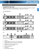
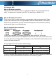
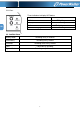
2. Installation and setup 2. Installation and setup NOTE: Before installation, please inspect the unit. Be sure that nothing inside the package is damaged. Please keep the original package in a safe place for future use. 2-1. Rear panel view 1K 1KL 1 2 3 4 AC input Output receptacle: connect to mission-critical loads.
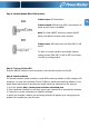
2-2. Setup the UPS Step 1: UPS input connection Plug the UPS into a two-pole, three-wire, grounded receptacle only. Avoid using extension cords. The power cord is attached to the UPS. The input plug is a NEMA 5-15P. EN Step 2: UPS output connection There are two kinds of output receptacles: programmable outlets and general outlet. Please connect non-critical devices to the programmable outlets and critical devices to the general outlets.
Step 4: Disable/Enable ROO/RPO function Contact open: UPS shuts down. EN Contact closed: UPS start-up (UPS is connected to AC power and AC power is available). Note: The local ON/OFF control by pressing On/Off button overrides the remote-control function. Contact open: UPS shuts down and Fault LED (3) will be ON. To return to normal operation, de-activate external remote contact (Fault LED (3) will be OFF) and restart the UPS by pressing button.
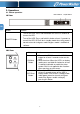
3. Operations 3-1. Button operation LED indicators On/Off button 1K View: EN Button Function • ON/OFF Button • Turn on the UPS: Press and hold button for at least 2 seconds to turn on the UPS. Turn off the UPS: Press and hold this button at least 2 seconds to turn off the UPS. UPS will be in standby mode when utility power is normal or transfer to bypass mode if bypass mode is enabled via software.
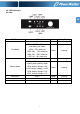
3-2. LED Indicators 1K View: EN UPS Status LED Color Lighting/Flashing LED1 Green Lighting Green Lighting LED2 Yellow Flashing LED4 to LED7 indicate battery capacity during battery mode. LED4: battery voltage > 26V LED5: battery voltage > 24.5V LED6: battery voltage > 23V LED7: battery voltage > 21V Green Lighting Low battery LED7 Green Flashing Battery replacement LED3 Red Flashing Fault LED3 Red Lighting Line Mode LED4 to LED7 indicate load level during line mode.
1KL View: Three indicators to display UPS status: EN UPS Status Indicators AC Mode Green LED lighting. Battery Mode Yellow LED flashing. Fault Red LED lighting. Off-mode charging. Green LED flashing. 3-3.
4. Troubleshooting If the UPS system does not operate correctly, please solve the problem by using the table below. Symptom Possible cause Remedy No indication and alarm even The AC input power is not Check if input power cord though the mains is normal. connected well. firmly connected to the mains. The AC input is connected to the UPS output. Plug AC input power cord to AC input correctly. UPS is overload Remove excess loads from UPS output.
6. Specifications MODEL CAPACITY INPUT Low Line Transfer Voltage Range EN Low Line Comeback High Line Transfer High Line Comeback Frequency Range Phase Power Factor OUTPUT Output voltage AC Voltage Regulation Frequency Range Frequency Range (Bat.