Online UPS PowerWalker VFI 1000CRM LCD PowerWalker VFI 2000CRM LCD PowerWalker VFI 3000CRM LCD Manual Uninterruptible Power Supply System EN
Table of Contents EN 1. Important Safety Warning ............................................................................................... 1 1-1. Transportation ....................................................................................................... 1 1-2. Preparation ........................................................................................................... 1 1-3. Installation .............................................................................................
1. Important Safety Warning Please comply with all warnings and operating instructions in this manual strictly. Save this manual properly and read carefully the following instructions before installing the unit. Do not operate this unit before reading through all safety information and operating instructions carefully 1-1. Transportation Please transport the UPS system only in the original package to protect against shock and impact. 1-2.
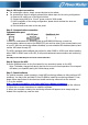
EN 1-5. Maintenance, service and faults The UPS system operates with hazardous voltages. Repairs may be carried out only by qualified maintenance personnel. Caution - risk of electric shock. Even after the unit is disconnected from the mains (building wiring outlet), components inside the UPS system are still connected to the battery and electrically live and dangerous.
2. Installation and setup NOTE: Before installation, please inspect the unit. Be sure that nothing inside the package is damaged. Please keep the original package in a safe place for future use. NOTE: There are two different types of online UPS: standard and long-run models. Please refer to the following model table.
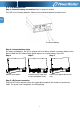
2-2. 1-3K Setup the UPS Step 1: External battery connection (Only for long-run models) This UPS is not including batteries. Please connect external batteries as below chart. EN To external battery Step 2: Connect battery wires For safety consideration, the UPS is shipped out from factory without connecting battery wires. Before install the UPS, please follow below steps to re-connect battery wires first. Step 1 Step 2 Step 3 Remove front panel. Connect the AC input and re-connect battery wires.
Step 4: UPS output connection For socket-type outputs, simply connect devices to the outlets. For terminal-type input or outputs, please follow below steps for the wiring configuration: a) Remove the small cover of the terminal block b) Suggest using AWG14 or 2.1mm2 power cords for 3KVA model. c) Upon completion of the wiring configuration, please check whether the wires are securely affixed. d) Put the small cover back to the rear panel.
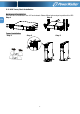
2-3. UPS Tower/Rack Installation EN Rack-mount Installation This UPS can be mounted in the 19” rack chassis. Please follow below steps to position this UPS.
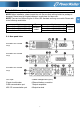
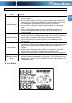
3. Operations 3-1. Button operation Button ON/Mute Button OFF/Enter Button Select Button ON/Mute + Select Button Function Turn on the UPS: Press and hold ON/Mute button for at least 2 seconds to turn on the UPS. Mute the alarm: When the UPS is on battery mode, press and hold this button for at least 5 seconds to disable or enable the alarm system. But it’s not applied to the situations when warnings or errors occur. Up key: Press this button to display previous selection in UPS setting mode.
Display Function Remaining backup time information Indicates the remaining backup time in pie chart. Indicates the remaining backup time in numbers. H: hours, M: minute, S: second EN Fault information Indicates that the warning and fault occurs. Indicates the warning and fault codes, and the codes are listed in details in 3-5 section. Mute operation Indicates that the UPS alarm is disabled. Output & Battery voltage information Indicates the output voltage, frequency or battery voltage.
3-3. Audible Alarm Description Battery Mode Low Battery Overload Fault Bypass Mode Buzzer status Sounding every 4 seconds Sounding every second Sounding twice every second Continuously sounding Sounding every 10 seconds 3-4. LCD display wordings index Abbreviation Display content Muted Yes Meaning ENA Enable DIS Disable ESC Escape HLS High loss LLS Low loss BAT Battery CF Converter TP Temperature CH Charger FU Bypass frequency unstable EE EEPROM error 3-5.
EN 110: presents output voltage is 110Vac 115: presents output voltage is 115Vac 120: presents output voltage is 120Vac (Default) 127: presents output voltage is 127Vac 02: Frequency Converter enable/disable Interface Setting Parameter 2 & 3: Enable or disable converter mode. You may choose the following two options: CF ENA: converter mode enable CF DIS: converter mode disable(Default) 03: Output frequency setting Interface Setting Parameter 2 & 3: Output frequency setting.
in parameter 3 is from -3V to -12V of the nominal voltage. (Default: -6V) 06: Bypass enable/disable when UPS is off Interface Setting Parameter 3: Enable or disable Bypass function. You may choose the following two options: ENA: Bypass enable DIS: Bypass disable (Default) 07: Bypass voltage range setting Interface Setting Parameter 2 & 3: Set the acceptable high voltage point and acceptable low voltage point for Bypass mode by pressing the Down key or Up key.
3-6. Operating Mode Description Operating mode Description LCD display Online mode When the input voltage is within acceptable range, UPS will provide pure and stable AC power to output. The UPS will also charge the battery at online mode. ECO mode Energy saving mode: When the input voltage is within voltage regulation range, UPS will bypass voltage to output for energy saving.
3-7. Faults Reference Code Fault event Fault code Bus start fail 01 Bus over 02 Bus under 03 Bus unbalance 04 Inverter soft start fail 11 Inverter voltage high 12 Inverter voltage Low 13 3-8.
4. Troubleshooting EN If the UPS system does not operate correctly, please solve the problem by using the table below. Symptom Possible cause Remedy No indication and alarm even The AC input power is not Check if input power cord though the mains is normal. connected well. firmly connected to the mains. The AC input is connected Plug AC input power cord to to the UPS output. AC input correctly. The icon and flashing on LCD display and alarm is sounding every second.
Symptom Battery backup time is shorter than nominal value Possible cause Batteries are not fully charged Batteries defect 15 Remedy Charge the batteries for at least 5 hours and then check capacity. If the problem still persists, consult your dealer. Contact your dealer to replace the battery.
5. Storage and Maintenance Operation EN The UPS system contains no user-serviceable parts. If the battery service life (3~5 years at 25°C ambient temperature) has been exceeded, the batteries must be replaced. In this case, please contact your dealer. Be sure to deliver the spent battery to a recycling facility or ship it to your dealer in the replacement battery packing material. Storage Before storing, charge the UPS 5 hours. Store the UPS covered and upright in a cool, dry location.
6. Specifications MODEL CAPACITY* INPUT Low Line Transfer Voltage Range Low Line Comeback High Line Transfer High Line Comeback Frequency Range Phase Power Factor OUTPUT Output voltage AC Voltage Regulation Frequency Range Frequency Range (Batt. Mode) Overload Current Crest Ratio Harmonic Distortion Transfer AC Mode to Batt. Mode Time Inverter to Bypass Waveform (Batt.