
Product Literature


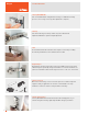
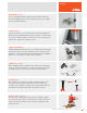
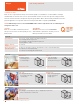
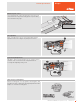
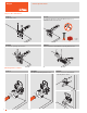
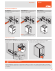
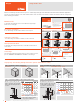
Table Of Contents

© 2019 Blum, Inc. Subject to technical modifications without notice
10
Hinges
Blum's Concealed hinges brochure makes it easy to use our Euro hinges. Each page shows information for both face frame and Framelessapplications.
The top row shows the hinge in a face frame cabinet and the center row shows it in a frameless cabinet. The bottom holds the overlay/reveal
tables and hinge part numbers.
Step 1 – Determine cabinet construction
Face frame Frameless
Step 2 – Determine the overlay or reveal
Overlay Partial/twin overlay Inset
Step 4 – Check minimum reveal table
All minimum reveal tables are
based on square edge door with
a 1 mm radius. A larger radius
or profile door will change the
minimum reveal required.
Trial application recommended
overlay
reveal
minimum reveal
19
1 rad
(
1
/
32
"
)
minimum reveal
19
1 rad
(
1
/
32
"
)
Step-by-step – the following example is based on a panel cabinet with an overlay
reveal
Frameless construction
To use Euro hinges in a frameless cabinet, use the center row.
Overlay and reveal tables
To determine the overlay and reveals, use the tables at the bottom of
each column.
Select hinge
Select the appropriate hinge from the bottom of each column. Screw-on,
press-in, EXPANDO and INSERTA are available for most hinges.
Face frame construction
To use Euro hinges in a face frame cabinet, use the top row.
Minimum reveal
To determine the minimum reveal, use the table in the upper right
hand corner of each page.
© 2017 Blum, Inc. Subject to technical modifications without notice
13
Hinges
Partial/twin overlay
Frame
Frameless
Half-cranked
Self close
Screw-on
71B3650
Press-in
71B3680
INSERTA
71B3690
Inset
Frame
NOTE: Application requires a half-cranked
hinge and mounting plate 175H5030.21
Frameless
Full-cranked Self close
Screw-on
71B3750
Press-in
71B3780
INSERTA
71B3790
Overlay
Frame
Frameless
▀ BLUMOTION integrated into the hinge cup
▀ Deactivation switch for small/light doors
▀ For door thicknesses up to 26 (1")
▀ Overload safety feature
▀ 86° angle restriction clip available (70T3553)
▀ Compatible with existing CLIP mounting
plates and hinge arm cover caps
H Overlay P S
0 14 15 16 17 18 12
21.5
3 11 12 13 14 15 15
24.5
4.5
9.5 10.5 11.5 12.5 13.5 16.5
26
6 8 9 10 11 12 18
27.5
9 5 6 7 8 9 21
30.5
3 4 5 6 7
Fixed
distance
=
11
B = boring distance
NOTE: 4.5 plate is only for use in frame
cabinets, 9 plate is only for panel cabinets
H Overlay P S
0 4.5 5.5 6.5 7.5 8.5 21.5
31
3 4 5 6 7
Fixed
distance
=
1.5
B = boring distance
H Reveal W P S
0
7 5 3 1 – 16
21.5
31
10 8 6 4 2 19
13 11 9 7 5 22
3 4 5 6 7
B = boring distance
H Reveal P S
0 4 3 2 1 – 30
39.5
9 4.5 3.5 2.5 1.5 0.5 30.5
40
3 4 5 6 7
Fixed distance:
0 = -7
9 = 1.5
B = boring distance
Features
H
W
B
overlay
37
T
66.5
13
H
66.5
T
B
overlay
13
H
B
overlay
66.5
T
13
H
H
W
B
reveal
37
66.5
T
13
H = 0
B
reveal
T + 38.5
T
68
13
B
H = 9
reveal
13
T
68
14
min.
Straight-arm Self close
Screw-on
71B3550
Press-in
71B3580
INSERTA
71B3590
EXPANDO
71B358E
Abbreviations
H = Plate height
P = Door protrusion
S = Side arm protrusion
W = Side panel width
Minimum reveal table
3 0.5 1.0 1.8 2.7 4.3
4 0.5 1.0 1.7 2.5 3.8
5 0.5 0.9 1.7 2.4 3.4
6 0.5 0.9 1.6 2.3 3.2
7 0.5 0.9 1.6 2.2 3.0
B
=
boring
distance
16 19 22 24 26
T
=
door thickness
Thickness greater than 26 trial recommended
CLIP top BLUMOTION 110
°
Minimum reveal table
3 0.6 1.0 1.3 1.7 2.5
4 0.6 1.0 1.3 1.6 2.4
5 0.6 1.0 1.2 1.5 2.2
6 0.6 1.0 1.2 1.4 2.0
B
=
boring
distance
16 18 19 20 22
T
=
door thickness
Step 3 – Find boring distance and mounting plate height
Based on your overlay use the
table to determine the mounting
plate height and boring distance
needed.
B = 6
H = 0
B = 5
H = 3
overlay = 17
overlay = 13
H Overlay P S
0 14 15 16 17 10
21
3 11 12 13 14 13
24
4.5
9.5 10.5 11.5 12.5 14.5
25.5
6 8 9 10 11 16
27
9 5 6 7 8 19
30
3 4 5 6
fixed
distance
=
11
B = boring distance
NOTE: 4.5 plate is only for use
in face frame cabinets, 9 plate
is only for panel cabinets
Using the Brochure