
Product Brochure

3
SECTION MODULE PAGE
HINGES
Modul
B
1
Version: 12-2004
All dimensions in millimeters (inch equivalents as shown).
GENERAL SPECIFICATIONS
H
B
T
W
R
OL
X
P
S
P
S
Minimum Reveal
19
1 rad
(
1
/
32
"
)
Minimum Reveal
19
1 rad
(
1
/
32
"
)
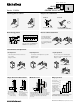
To install slide hinge on
to the mounting plate,
tighten rear fixing screw.
Loosen rear fixing screw
and pull hinge forward to
remove.
¯8
45
9.5
35
B
Door
C
Mounting plate-to-cabinet
Hinge-to-door attachment
Screw-on
Use #6 wood screws
Press-in
Pre-attached dowels,
install with Blum MINIPRESS
Three-dimensional adjustment
Side adjustment
Turn front screw to increase or decrease
door overlay.
Range = +/-2mm
Height adjustment
Loosen screw(s) on the mounting plate.
Adjust door to position and tighten screws.
Range = +/-3mm
Depth adjustment
Loosen back screw. Adjust door to position
and tighten screw.
Range = +/-2mm
Hinge dimension abbreviations Minimum reveal Hinges per door
A minimum reveal per door is required to keep the door
from binding and varies depending on door thickness
(see Minimum reveal table for each hinge). Minimum
reveal based on outside door edge with radius
of 1 (1/32").
B
H
OL
P
= Boring distance
= Mounting plate height
= Door overlay
= Door protrusion
(at max opening)
R
S
T
W
X
= Reveal
= Hinge arm protrusion
= Door thickness
= Side panel width
= Fixed cup distance
Screw-on EXPANDO
Blum boring pattern
Two piece mounting plate
One piece mounting plate
Door-to-cabinet attachment
* only for use with select Blum hinges
X
2 3
4 5
20"
40"
60"
80"
100"
Y
15
lb.
15-30
lb.
30-45
lb.
45-60
lb.
This chart can serve
as a guide for deter-
mining the number
of hinges per door.
Note that door weight
can also determine
the number of hinges
required.
X = Door height
Y = Number of hinges
* The distance between the two hinges must be greater
than the width of the door for maximum stability.
*
Cup centerpoint is the MINIPRESS or
MINIDRILL fence depth position.
C Cup centerpoint
20.5 21.5 22.5 23.5 24.5 25.5
3 4 5 6 7* 8*
B Bore distance