WATER SOURCE HEAT PUMP MODELS: INSTALLATION INSTRUCTIONS GTB1-A GTA3600UD1AA GTA4860UD1AA GTADP-3642-B GTADP-3642-C GTADP-4860-C GTC36S2-ADCX GTC48S2-ADCX GTC60S2-ADCX GTC36S2-ADNX GTC48S2-ADNX GTC60S2-ADNX Blower Section Coil Section Coil Section Coil Section Coil Section Coil Section Compressor Section Compressor Section Compressor Section Compressor Section Compressor Section Compressor Section MIS-2830 Earth Loop Fluid Temperatures 25° - 110° Ground Water Temperatures 45° - 75° BMC, Inc.
CONTENTS Getting Other Informations and Publications............... 3 General Information Geo-Trio (GT Series) Water Source Nomenclature..................................................... 4 Blower Conversion & Line Power Connect............................. 15 Application and Location General ............................................................................. 18 Shipping Damage.................................................................... 18 Application ...................................
GETTING OTHER INFORMATION AND PUBLICATIONS These publications can help you install the air conditioner or heat pump. You can usually find these at your local library or purchase them directly from the publisher. Be sure to consult current edition of each standard.
Geo-Trio™ GT Series Geothermal / Water Source Heat Pump Nomenclature “A” Coil Section GT A 3600 UD 3600 (3 Ton) 4860 (4 & 5 Ton) Geo-Trio “A” = Coil Section 1 A Revision Level Series A A = E Coated Coils Option Fossil Fuel “A” Coil Section GT ADP – Geo-Trio 3642 – B B = 17.50" Wide Furnace C = 21.
TABLE 1 — INDOOR BLOWER PERFORMANCE (RATED CFM) MODEL k Rated ESP l MAX ESP m Continuous Airflow n Mild Climate Operation in Part Load Cooling GTC36S2 0.15 0.60 600 GTC48S2 0.20 0.60 750 GTC60S2 0.20 0.60 900 o Part Load Airflow Full Load Airflow p Electric Heat Airflow q Minimum Air Filter Face Area Ft.2 700 850 1200 1300 2.6 875 1075 1500 1600 3.2 1050 1300 1800 1800 3.
TABLE 4 WATER COIL PRESSURE DROP Model GTC36S2 GTC48S2 GPM PSID Ft. Hd. 3 0.1 0.23 4 0.5 5 GTC60S2 PSID Ft. Hd. PSID Ft. Hd. 1.15 0.9 2.08 1.2 2.77 1.4 3.23 6 1.7 3.92 2.3 5.31 7 2.3 5.31 3.2 7.38 2 4.61 8 3.1 7.15 4.1 9.46 2.5 5.77 9 4.1 9.46 5.1 11.77 3.2 7.38 10 6.1 14.07 3.9 9.00 11 7.1 16.38 4.7 10.84 12 8.2 18.92 5.5 12.69 13 9.4 21.69 6.4 14.76 14 10.6 24.45 7.3 16.84 15 8.1 18.69 16 9 20.76 17 9.9 22.
Manual Page 2100-537I 7 of 54 3 5/16" 2 3/16" 17 5/8" 15 11/16" 2 3/16" 1 1/2" 30" 5 1/8" 3 1/2" OVERFLOW MAIN DRAIN LIQUID CONNECTION SUCTION CONNECTION HORIZ. OVERFLOW K.O. HORIZ. MAIN DRAIN K.O. 19 15/16" 22" 21 5/8" 13 5/8" 10 15/16" 7 1/4" 1 13/16" CONDENSATE OVERFLOW WIRES COATED DRAIN PAN COIL 2 3/4" 27 15/16" MIS-2818 PRIMARY DRAIN HOLE +.125 - .000 MIS-2876 A 2.25 +.125 16.13 HEIGHT -.000 SECONDARY DRAIN HOLE +.125 20.50 WIDTH -.
FIGURE 1B – GTADP****-* FOSSIL FUEL ADP COIL SECTION DIMENSIONS FIGURE 1B - GTADP****-* FOSSIL FUEL ADP COIL SECTION DIMENSIONS DIMENSION GTADP-3642-B "A" "B" "C" "D" "E" "F" "G" "A" 3/4" TYP SUCTION CONNECTION 3/4" TYP 3/4" TYP 21 1/4" "C" 5 1/4" "B" LIQUID CONNECTION "E" OVERFLOW MAIN DRAIN 17 5/8" 25 1/2" 7 1/4" 2 1/8" 3 7/8" 13 7/8" 15 5/8" GTADP-3642-C GTADP-4860-C 21 1/8" 27 1/2" 6 3/4" 2 1/2" 4 1/4" 16 7/8" 18 5/8" "D" OVERFLOW 6 1/16" MAIN DRAIN 1 5/8" "F" Manual 2100-537I Page 8
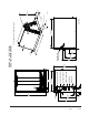
FIGURE 1C – GTB1-A BLOWER SECTION DIMENSIONS 16 3/8" 30" 13 1/4" LOW VOLTAGE ENTRANCE 3 5/8" 22" 1 1/4" HIGH VOLTAGE K.O.
Manual 2100-537I Page 10 of 54 2 1/2" A 16 1/16" 12 1/4" 9 5/8" 1 7/8" 6 15/16" 1 3/4" 3" B WATER IN LIQUID LINE DESUPERHEATER WATER OUT DESUPERHEATER WATER IN SUCTION LINE WATER OUT 22 1/16" 23 1/16" 30" 8" 4 13/16" 16 15/16" 1 15/16" MODEL GTC36S2 GTC48S2 GTC60S2 FIGURE 1D – GTC**S2-D COMPRESSOR SECTION DIMENSIONS DIM. B 4 1/8" 3 7/8" 3 3/4" HIGH VOLTAGE OPTIONAL FLOW CENTER WIRE ENTRANCE HIGH VOLTAGE UNIT POWER ENTRANCE LOW VOLTAGE WIRE ENTRANCE DIM.
Manual Page 2100-537I 11 of 54 21" 15 5/8" 23" 65 5/8" 21 5/8" 3/4" LEFT SIDE 24 9/16" 30" AIR ENTRANCE (UPFLOW ONLY) 31 1/4" 27 7/8" 37 1/16" 51 1/4" 55" 23 7/16" "A" 59 11/16" 61 5/8" REFRIGERANT CONNECTIONS FRONT 22" MODEL GTC36S2 GTC48S2 GTC60S2 30 9/16" 33 1/4" 18 13/16" 28 15/16" 25 3/4" 37 7/8" WATER IN DESUPERHEATER INLET DESUPERHEATER OUTLET WATER OUT OVERFLOW DRAIN OUTLET RIGHT SIDE 24 9/16" 30" AIR ENTRANCE (UPFLOW ONLY) LOW VOLTAGE HIGH VOLTAGE LOW VOLTAGE
Manual 2100-537I Page 12 of 54 7 27 8 " Left Side View Evaporator Opening GTHZ1 Horizontal Drain Pan (Req'd) 7 19 8 " Evaporator Section 1 1 1 28" 32" 22 8 " 1 30" 12" 3 4" 1 31 4 " Blower Section 8" 43 8 " 3 Low Voltage Entrance 1 3 1 28 8 " 21" 18 4 " 1 15" Horiz.
Cond. Coil Water In Return Desuper. Water In Desuper. Water Out 3/8" Line Set Cond. Coil Water Out 7/8" Line Set Main Drain Secondary Drain Evap. Coil Supply Return Blower Air Blower in Shipped Position Return Control Panel Upflow Position Bottom return upflow and top return counterflow filter provision must be field supplied One FR23 (16 x 25 x 1) or field supplied equivalent required for upflow side return installation Air Filter Required Cond. Coil Water In Desuper. Water In Desuper.
Manual 2100-537I Page 14 of 54 Evap. Coil < > Refrigerant Secondary Drain Connections Blower in Alternate Position Blower Air Supply Blower in Shipped Position See additional information on Pages 19 & 20. For horizontal attic or crawl space installations filter arrangement must be field supplied & should be located in readily accessible location for the user. Bottom return for upflow and top return for downflow must be field supplied.
BLOWER CONVERSION FROM UPFLOW TO COUNTERFLOW OR HORIZONTAL RIGHT DISCHARGE BLOWER LINE POWER CONNECTION Following the directions on Figure 3 for counterflow and horizontal right discharge, the indoor blower must be removed and turned over in its mounting configuration. The first is in “stacked” configurations, the blower can be plugged into an electrical connection from the bottom of the compressor (GTC**S2 Model Unit). This will work for either upflow or counterflow applications.
Manual 2100-537I Page 16 of 54 MIS-2842 A REMOVE BOTH FRONT PANELS 1 5 4 REINSTALL FRONT FILL PLATE ROTATE BLOWER AND SLIDE INTO BOTTOM OFFSETS 3 2 6 REINSTALL BOTH FRONT PANELS REMOVE (2) SCREWS FROM FRONT FILL PLATE AND SLIDE BACK FILL PLATE OUT OF CABINET REMOVE (2) SCREWS SECURING BLOWER AND SLIDE BLOWER OUT OF CABINET FIGURE 3 – BLOWER CONFIGURATIONS REINSTALL (2) SCREWS SECURING BLOWER TO FRONT FILL PLATE DISCARD BACK FILL PLATE
Manual Page 2100-537I 17 of 54 PLUG BLOWER POWER CONNECTOR INTO POWER PLUG PROTRUDING THROUGH CONDENSER BASE FOR BOTH UPFLOW AND COUNTERFLOW STACKED CONFIGURATIONS FIGURE 4 – BLOWER POWER CONNECTIONS MIS-2843 REMOVE SUPPLIED WIRE HARNESS AND STRAIN RELIEF BUSHING FROM BLOWER POWER PLUG. ROUTE WIRE HARNESS THROUGH STRAIN RELIEF AND INTO ELECTRICAL BOX TO MAKE FIELD POWER CONNECTION MOUNT FIELD SUPPLIED SINGLE GANG ELECTRICAL BOX ALIGNED OVER HIGH VOLTAGE K.O.
APPLICATION AND LOCATION GENERAL The GT Series Geothermal Heat Pumps feature three sections (GTA - Air Coil Section, GTB - Blower Section and GTC Compressor Section) which cover upflow (bottom, right/leftside return), counterflow and horizontal (left and right-hand discharge) applications. The individual sections are shipped internally wired, requiring duct connections, thermostat wiring, 230/208 volt AC power wiring, refrigerant line connections and water piping.
CAUTION NEVER OPERATE MORE THAN 10KW STRIP HEAT WITH GEOTHERMAL HEAT PUMP OPERATIONAL. USE ADDITIONAL KW STRIP HEAT BEYOND 10KW ONLY IN EMERGENCY HEAT MODE. TABLE 5 ELECTRICAL HEAT SPECIFICATIONS For Use Heater With Package All GTC*S2 Models Heater Package 240 Volts 208 Volts KW Amps BTUH KW Amps BTUH Minimum Circuit Ampacity Maximum HACR Circuit Breaker Field Wire Size + 8604-080 240/208-60-1 5.0 20.8 17,065 3.75 18.0 12,799 26.0 30 #10 8604-081 240/208-60-1 9.8 40.
TABLE 6 FILTER SIZING CHART Filter Nominal Size Surface Area FT2 Filter Type Airflow CFM Capability @ 300 FPM Velocity Airflow CFM Capability @ 500 FPM Velocity Airflow CFM Capability @ 625 FPM Velocity Not Recommended Not Recommended 10" X 20" X 1" 1.39 415 12" X 20" X 1" 1.67 500 14" X 20" X 1" 1.94 580 14" X 25" X 1" 2.43 16" X 20" X 1" 2.22 16" X 25" X 1" 2.78 20" X 20" X 1" 2.78 840 20" X 25" X 1" 3.47 1050 24" X 24" X 1" 4.00 1200 10" X 20" X 2" 1.
AIR FILTER APPLICATIONS FIGURE 5A FIGURE 5B COUNTERFLOW UPFLOW AIRFLOW SINGLE FILTER CONFIGURATION "V" FILTER CONFIGURATION AIR FIL TE R R TE R TE FIL FIL AI AIR R AIR FILTER FIL TE * "A" FILTER CONFIGURATION * AIRFLOW AIRFLOW A IR AIR FILTER AIRFLOW CENTRAL RETURN GRILLE(S) (ONE OR MULTIPLE) AIRFLOW A IR AIR FILTER CENTRAL RETURN GRILLE(S) (ONE OR MULTIPLE) R FIL TE * R * * SIDE INLET(S); ONE OR BOTH SIDES OR IN COMBINATION WITH BOTTOM INLET AIR FILTER AIRFLOW AIR FI
WIRING INSTRUCTIONS GENERAL All wiring must be installed in accordance with the National Electrical Code and local codes. In Canada, all wiring must be installed in accordance with the Canadian Electrical Code and in accordance with the regulations of the authorities having jurisdiction. Power supply voltage must conform to the voltage shown on the unit serial plate. A wiring diagram of the unit is attached to the inside of the electrical cover.
Manual Page 2100-537I 23 of 54 R B W1 W2 R L G Y1 Y2 O/B W2 W1/E R L G Y1 Y2 O/B W1 W2 1 3 A A Optional Wiring Field Installed Wiring Optional Motorized Valve With End Switch (Use with Water/ Water Loop) 2 Y2 Y1 G C C C NOTE: "O/B" TERMINAL MUST BE PROGRAMMED TO ENERGIZE IN COOLING NOTE: W1=FIRST STAGE AUX. HEAT W2=SECOND STAGE AUX.
GROUND LOOP (EARTH COUPLED WATER LOOP APPLICATIONS) NOTE: Unit shipped from factory with 75 PSIG low pressure switch wired into control circuit and must be rewired to 55 PSIG low pressure switch for ground loop applications. This unit is designed to work on earth coupled water loop systems, however, these systems operate at entering water (without antifreeze) temperature with pressures well below the pressures normally experienced in water well systems.
START UP PROCEDURE FOR GROUND LOOP SYSTEM 8. Start the unit in cooling mode by moving the thermostat switch to cool. Fan should be set for AUTO. 1. Be sure main power to the unit is OFF at disconnect. 9. Check the system refrigerant pressures against the cooling refrigerant pressure table in the installation manual for rated water flow and entering water temperatures. If the refrigerant pressures do not match, check for airflow problem then refrigeration system problem. 2.
FIGURE 8 FIGURE 8 Thermometer Thermometer NOTE: Slide retaining cap back to expose double o-rings. petroleum jellytotoexpose o-rings NOTE: SlideApply retaining cap back to prevent damage Apply and aidpetroleum in insertion double o-rings.
GROUND WATER (WELL SYSTEM APPLICATIONS) NOTE: Unit shipped from factory with 60 PSIG low pressure switch wired into control circuit for ground water applications. WATER CONNECTIONS It is very important that an adequate supply of clean, noncorrosive water at the proper pressure be provided before the installation is made. Insufficient water, in the heating mode for example, will cause the low pressure switch to trip, shutting down the heat pump.
the piping is not undersized, which would create too much pressure due to friction loss. High pressure losses due to undersized pipe will reduce efficiency and require larger pumps and could also create water noise problems. The pressure requirements put on the pump are directly affected by the diameter of pipe being used, as well as, by the water flow rate through the pipe. The worksheet included in Manual 2100-078 should guarantee that the well pump has enough capacity.
SYSTEM START UP PROCEDURE FOR GROUND WATER APPLICATIONS 1. Be sure main power to the unit is OFF at disconnect. 2. Set thermostat system switch to OFF, fan switch to AUTO. 3. Move main power disconnect to ON. Except as required for safety while servicing – DO NOT OPEN THE UNIT DISCONNECT SWITCH. 4. Check system airflow for obstructions. A. Move thermostat fan switch to ON. Blower runs. B. Be sure all registers and grilles are open. C. Move thermostat fan switch to AUTO. Blower should stop. 5.
4. Scale Formation. Of all the water problems, the formation of scale by ground water is by far the most common. Usually this scale is due to the formation of calcium carbonate but magnesium carbonate or calcium sulfate may also be present. Carbon dioxide gas (CO2), the carbonate of calcium and magnesium carbonate, is very soluble in water. It will remain dissolved in the water until some outside factor upsets the balance. This outside influence may be a large change in water temperature or pressure.
C. If possible, use a submersible pump suspended in the dry well casing. Jet pumps and other types of suction pumps normally consume more electrical energy than similarly sized submersible pumps. Pipe the unit the same as a water well system. D. Size the pump to provide necessary GPM for the ground water heat pump. A 12 GPM or greater water flow rate is required on all models when used on this type system. E.
DESUPERHEATER DESCRIPTION The system is designed to heat domestic water using heat recovered from a water source unit’s hot discharge gas. LOCATION Because of potential damage from freezing or condensation, the unit must be located in a conditioned space, therefore the unit must be installed indoors. Locate the storage tank as close to the geothermal heat pump and pump module as the installation permits. Keep in mind that water lines should be a maximum of 25 feet long measured one way.
DESUPERHEATER OPERATION OF THE HEAT RECOVERY UNIT The pump module is a very simple device containing basic controls and a circulating pump. Heat is transferred from the hot refrigerant (discharge gas) to the cool water. The operation of the Desuperheater Pump Module is controlled first by the operation of the Geothermal Heat Pump and secondly by internal controls within the Pump Module.
FIGURE 14 WIRING DIAGRAM COMPRESSOR CONTACTOR SIGNAL FROM GEOTHERMAL LOGIC CONTROL 3 AMP FUSE NC LINE VOLTAGE N OUTLET WATER SENSORS C NO INLET TSTAT 3 CONTROL LOGIC PUMP OUTLET 2 POWER 1 N DESUPERHEATER PUMP PLUG L BLACK RED C 24VAC BLACK C R RED R DESUPERHEATER PUMP CONTROL Y GTC LOW VOLTAGE TERMINAL STRIP BLACK BLACK BLACK BLACK OVER TEMP.
Manual Page 2100-537I 35 of 54 EXISTING WATER HEATER L.P.
Manual 2100-537I Page 36 of 54 OUT ADDITIONAL HOT WATER STORAGE TANK. NOT ELECTRICALLY CONNECTED DRAIN EXISTING WATER HEATER L.P.
DESUPERHEATER CONTROL BOARD SEQUENCE OF OPERATION The desuperheating control board will make a determination whether or not to energize the pump relay inclusive on the control board. A. It will constantly monitor inputs from two temperature sensors, Inlet & Outlet water sensors. B. It will constantly monitor the Y signal. C. Upon acknowledgment of Y signal, and following two minutes, the control board will energize the pump relay. D.
SEQUENCE OF OPERATION BLOWER PART LOAD HEATING (No Electric Heat) Blower functions are all controlled through 24 VAC input signals from the control thermostat and 208/230 VAC being supplied to the motor continuously. When thermostat system is placed in HEAT, the reversing valve solenoid is no longer energized.
SEQUENCE OF OPERATION HIGH PRESSURE SWITCH UNDER & OVER VOLTAGE PROTECTION (TERMINALS HP1 & HP2) Circuit will be proved as “closed” prior to energizing “A” or “CC” terminals. If pressure switch opens, compressor will go into soft lockout mode and compressor operation will be terminated; green fault light illuminated. Logic control will then go through 5-minute delay on break + random start sequence. If no fault found on next run cycle, compressor will continue operation.
FIGURE 17 — COMPONENT LOCATION WATER COIL LOW PRESSURE SWITCHES REVERSING VALVE HIGH PRESSURE SWITCH EXPANSION VALVE DESUPERHEATER COIL LOW VOLTAGE FILTER/DRIER COMPRESSOR PUMP UNIT HIGH VOLTAGE PUMP MODULE HIGH VOLTAGE MIS-2838 FIGURE 18 — CONTROL PANEL TERMINAL STRIP GEOTHERMAL LOGIC CONTROL DESUPERHEATER CONTROL BOARD COMPRESSOR CONTACTOR GROUND TERMINALS PUMP MODULE POWER CONNECTION CIRCUIT BREAKERS RELAY PLUG COMPRESSOR CAPACITOR MIS-2837 Manual 2100-537I Page 40 of 54
FIGURE 19 Manual Page 2100-537I 41 of 54
REFRIGERANT CHARGE 3. Final torque should be achieved. Use the appropriate size wrench in conjunction with a second (backing) wrench to ensure that fittings do not spin or twist on the copper refrigerant lines. Use the following torque rates: 3/8" Lineset – 22-25 ft. lbs. (30-35 Nm) 7/8" Lineset – 44-47 ft. lbs.
REFRIGERANT CHARGE GENERAL – GTADP COIL SECTIONS GENERAL (GTADP Add-On Coils) These instructions are intended as a general guide and do not supersede the coil manufacturer’s installation instructions or local codes in any way. Read the manufacturer’s installation manual and all “WARNING” statements prior to installing the evaporator coil. The following is needed, in addition to the evaporator coil. 1. Line Set Stub Kit with Single Pair Ends – Bard Part No. GTLS-SK2-1 2.
REFRIGERANT CHARGE These units require R-410A refrigerant and Polyol Ester. GENERAL: SAFETY PRACTICES: 1. Never mix R-410A with other refrigerants. 1. Use separate service equipment to avoid cross contamination of oil and refrigerants. 2. Use gloves and safety glasses, Polyol Ester oils can be irritating to the skin, and liquid refrigerant will freeze the skin. 2. Use recovery equipment rated for R-410A refrigerant. 3. Never use air and R-410A to leak check; the mixture may become flammable.
FIGURE 21 PRESSURE TABLES Model Return Air Temperature Pressure 75° DB 62° WB FULL LOAD COOLING — Fluid Temperature Entering Water Coil °F 30°F 35°F 40°F 45°F 50°F 55°F 60°F 65°F 70°F 75°F 80°F 85°F 90°F 95°F 100°F 105°F 110°F Low Side High Side 108 148 111 163 113 177 116 192 118 206 121 221 123 235 126 250 128 264 129 286 129 309 130 331 131 353 131 376 132 398 132 420 133 442 80° DB 67° WB Low Side High Side 116 152 118 167 121 182 124 196 126 211 129 226 13
Loose Terminals Faulty Wiring Blown Fuse or Tripped Breaker Power Failure Low Voltage Compressor Overload Start Capacitor Run Capacitor Potential Relay Thermostat Low Voltage Control Transformer Loose Terminals Faulty Wiring Indoor Blower Relay Discharge Line Hitting Inside of Shell Contactor Coil Excessive Operation Costs Ice in Water Coil Aux. Heat on I.D.
SERVICE SERVICE HINTS COMPRESSOR SOLENOID 1. Caution owner to maintain clean air filters at all times. Also, not to needlessly close off supply and return air registers. This reduces airflow through the system, which shortens equipment service life as well as increasing operating costs. (See Sequence of Operation on Pages 37 & 38 for function.) A nominal 24-volt direct current coil activates the internal compressor solenoid. The input control circuit voltage must be 18 to 28 volts ac.
TROUBLESHOOTING GE ECM 2.3™ MOTORS CAUTION: Disconnect power from unit before removing or replacing connectors, or servicing motor. To avoid electric shock from the motor’s capacitors, disconnect power and wait at least 5 minutes before opening motor.
TROUBLESHOOTING GE ECM™ MOTORS CONT’D. Replacing ECM Control Module To replace the control module for the GE variable-speed indoor blower motor you need to take the following steps: 1. You MUST have the correct replacement module. The controls are factory programmed for specific operating modes. Even though they look alike, different modules may have completely different functionality. USING THE WRONG CONTROL MODULE VOIDS ALL PRODUCT WARRANTIES AND MAY PRODUCE UNEXPECTED RESULTS. 2.
TROUBLESHOOTING GE ECM™ MOTORS CONT’D.
GROUND SOURCE HEAT PUMP GROUND SOURCE HEAT PUMP PERFORMANCE REPORT PERFORMANCE REPORT This performance check report should be filled out by installer and retained with unit. This performance check report should be filled out by installer and retained with unit. DATE 1. TAKEN BY: UNIT: Mfgr Model No. S/N THERMOSTAT: Mfgr Model No. P/N 2. Person Reporting 3. Company Reporting 4. 5. Installed By User’s (Owner’s) Name Address 6. Unit Location Date Installed WATER SYSTEM INFORMATION 7.
THE FOLLOWING INFORMATION IS NEEDED CHECK PERFORMANCE UNIT. THETO FOLLOWING INFORMATIONOF IS NEEDED TO CHECK PERFORMANCE OF UNIT. Cooling 9. 10. 11. 12. 13. 14. 15. 16. 17. 18. 19. 20. 21. 22. 23.
208/230-60-1 2 3 4 7 5-PIN MOTOR POWER PLUG GREEN BLACK 1 RED 4-PIN UNIT 7 POWER PLUG 1 Indoor Blower Motor 2 3 RED BLACK 1 4 5 MODEL 1 2 OFF OFF ON OFF OFF ON 5 6 OFF OFF ON OFF OFF ON 3 4 7 7 240V 7 208V COM ADJUSTMENT TAPS NONE "+10%" "-10%" NONE OFF OFF ON OFF OFF ON ON ON NOTE: SWITCH #4 MUST BE TURNED ON WHEN BLOWER IS CONVERTED TO COUNTERFLOW OR HORIZONTAL RIGHT DISCHARGE 16-PIN BLOWER CONTROL PLUG 7 3 9 C 12 CIRCUIT BREAKER 8 3A R RED/WHITE BLACK/WHITE 10 RED
29 24 25 C High Speed Solenoid S N RED 40 40 L 30 17 43 34 35 RED 21 23 36 26 21 CC A O L Y R C RED/WHITE 35 35 13 R1 C2 3 2 1 CO2 CO FS2 FS LP2 LP1 GRAY GRAY BLACK 37 RED RED BLUE BLUE BLUE BLUE HIGH PRESSURE SWITCH RED RED 208/230-60-1 LINE POWER FIELD CONNECTED STATUS 5 HP1 HP2 27 1 6 Status = Green Status LED will blink in normal operation. 4 F.S. = Red fault light illumninated when fault indicated. 3 L.P.