
Operation Manual


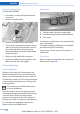

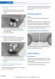

5. Remove the connecting line from the clip
on the bulb holder.
6. Release the catch at the top on the con‐
nector of the connecting line and remove
the connector from the bulb holder.
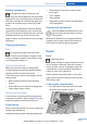
Replacing the bulbs
1. Loosen the four fasteners, arrow 1, on the
bulb holder and remove the bulb holder
from the tail lamp, arrow 2.
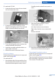
2. Press the defective bulb gently into the
socket, turn counterclockwise and remove.
3. Proceed in the reverse order to insert the
new bulb and attach the bulb holder. Make
sure that the bulb holder engages in all fas‐
teners.
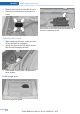
Installing the tail lamp
1.
Connect the connecting line to the tail
lamp and secure the bulb holder in the clip.
2. Make sure that the foam rubber sealing
ring is on the centering pin, arrow 2, and is
not damaged.
3. Position and firmly press the outer part of
the tail lamp onto the rubber mount, ar‐
row 1 and the inner part onto the centering
component, arrow 2. Make sure that the
tail lamp engages in the rubber mount.
4. Screw the tail lamp on with the two nuts.
5. Fit the cover in place and screw onto the
fastener. Make sure that the tubular seal is
not pinched.
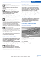
Lamps in the trunk lid
General information
Follow the general instructions on Lamps and
bulbs, refer to page 206.
Reversing lamps: 16-watt bulb, PW16W.
Inner brake lamps: 21-watt bulb, H21W
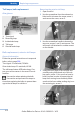
Accessing the lamps
1.
Use the screwdriver from the onboard ve‐
hicle tool kit to loosen and completely re‐
move the six screws on the trim.
2. Carefully loosen the trim from the trunk lid,
starting at the edge and working toward
the area around the recessed grips. Make
sure that the trim does not become stuck.
3. Carefully swing out the trim.
Seite 213
Replacing components Mobility
213
Online Edition for Part no. 01 40 2 926 810 - X/13