
Technical data


T
iming gear adjustment
Adjust Valve clearance
24
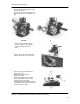
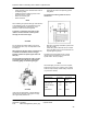
Adjust valve clearance and timing
NOTE
Carry out the testing and adjusting when the engine
is cold.
The following must be carried out:
- Set the decompression lever to “0”
- Remove cylinder head cover
- Crank the engine in rotation direction until the
compression resistance can be felt
- Check valve clearance between rocker arm and
valve shaft with a feeler gauge
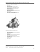
- In the case of incorrect valve clearance, loosen
the lock nut and adjust the set screw with a
screwdriver so that the feeler gauge can be
pulled through between the rocker arm and the
valve shaft with noticeable resistance after the
nut is
re-tightened
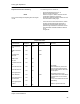
Repair Data Valves
Cylinder Head Dimension
D7 nominal
values
Max. allowable
wear (mm)
Remarks
Valve clearance
cold
Intake valve stem
dia
Exhaust valve
stem dia
Intake valve
disc dia
Exhaust valve disc
dia
Valve sit back max
Valve sit back min
Valve guide bore
Outer diameter
Valve guide bore in
cylinder head
Valve guide press
in force
mm
mm
mm
mm
mm
mm
mm
mm
mm
mm
kp
0.15
7
7
30.5
30.5
0.70
0.45
7
10
10
100
0.05
0.05
0.05
CAUTION!
Valve sit back may not be less
than 0.45 mm as otherwise the
danger exists that the valve disc
hits the piston.
The sealing surface of the
cylinder head can be reworked to
a maximum of 0.5 mm if the sit
back of
0.7 mm is exceeded due to valve
seat milling.
With the cylinder head cold.