
Technical data


G
enerator and generating equipment
36
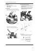
- Flatten lockwasher/cable clip F (renew on
assembly), securing stator cable to bearing
housing (SW 13)
- Remove bolts G (7 mm) and lift off stator
Notes on Assembly
- Grip magnet (rotor) firmly by hand and carefully
place in flywheel, taking care to avoid jamming
by lowering unevenly. If necessary, tap magnet
with judicious use of soft-faced hammer
-
CAUTION
Do not hit magnet directly with a metal tool,
or heat flywheel (loss of magnetism can
result)
- Lay stator harness close to bearing housing, to
avoid contact with flywheel
- Bend tags of stator cable end slightly to ensure
firm fit before fitting to plug. Note fitted positions
of cables.
Operation check and fault-finding
- Check that cable insulation is in order
- Examine stator windings for possible damage
- Check all connections for corrosion and ensure
that connections are firm
- The generator generates current without
mechanical contacts and has no bearings.
Faults, therefore, generally arise from short-
circuits, loose or wrong connections in electrical
circuit of boat.
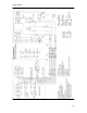
When faults occur, first check circuit, then
operation of generator in situ (see wiring
diagram)
Required for testing are:
Voltmeters 0-15 DC, 0-250 AC
Ammeter 0-40
Test/amp 12V
Fault Possible Cause Check Remedy
Control lamp remains lit
after starting engine
Faulty impulse
transmitter. Faukts in
boat circuit (e.g. short
circuits)
No charge
Check impulse
transmitter (see section
checking procedure 1)
Check charge (see
checking procedure 2)
Check boat circuit for
faults.
Renew impulse
transmitter
See 2 (this table)
No charge
Defective control unit
Faulty generator (control
unit is usually also
defective)
Check voltage (see
checking procedure 3)
Check voltage (see
checking procedure 3)
Depending on result
renew control unit and/or
generator
Renew generator rotor
and/or stator. Possibly
renew control unit.