Instruction Manual Model 1420 Video Microscope 2955 Kerner Blvd., #2 San Rafael, CA 94901 Ph: 415-453-9955 Fx: 415-453-9956 www.berkeleynucleonics.
1 INTRODUCTION ..................................... 3 1.1 Package contents............................................................ 3 1.2 Basic functions ............................................................... 3 1.3 Computer requirements.................................................. 4 1.4 Installing the software .................................................... 5 1.4.1 Installing the Hauppauge WinTV video card...................... 5 1.4.2 Installing the ADS USB2.0 capture peripheral ....
6.1 6.2 6.3 6.4 6.5 6.6 Video compression ....................................................... 26 Recording speed ........................................................... 26 Buffering ........................................................................ 26 Pre- and post trigger recording ................................... 28 Starting and stopping recording.................................. 29 Deinterlacing ................................................................. 30 7 PROBES ............
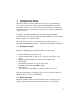
1 INTRODUCTION The Model 1420 is an inverted fluorescence microscope with built-in video camera, fluorescence filter, pulsed Light-Emitting Diode (LED) illuminator, motorized x-y traverse and focusing actuator. It can directly image fluorescent or non-fluorescent samples on a standard video monitor or video recorder. In addition, the Model 1420 includes an advanced programmable synchronization unit with four inputs and three outputs for synchronizing image acquisition to external events.
acquisition, processing and storage. You can use the instrument in several ways: » As a stand-alone video microscope. Connect the video output from the Model 1420 to an analog video monitor or VCR through the BNC or the S-video outputs on the rear panel. You can now focus, traverse and adjust illumination intensity by the controls on the front panel while observing the image on the monitor.
composite video signal. The video signal is digitized by a DirectX9.0 compliant PCI video capture card (Berkeley Nucleonics optionally supplies a Hauppauge PCI video card) or USB2.0 video capture peripheral (BNC optionally supplies an ADS video capture peripheral), capable of digitizing and storing uncompressed VGA resolution video on disk. Many PC video input devices include on-board image compression hardware, converting the video stream into various compressed video formats.
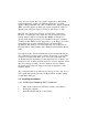
4. 5. 6. 7. 8. When "Found New Hardware Wizard" pops up check "Install the software automatically (Recommended)" (this may vary with Windows version). You can also force Windows to look on the CDROM for the drivers. A screen should pop up that says "The software you are installing for this hardware Hauppauge Win/TV 878/9 VFW Window Driver has not passed Windows Logo testing...
1.5 Setting up the Model 1420 1. Plug the power cable from the back of the Model 1420 into a 90 240 VAC power outlet. 2. Connect the 9-pin D-sub serial connector on the back of the Model 1420 to a free serial port on the PC. You may use a USB/RS232 converter device if your computer does not have a RS232 port. BNC will optionally provide a converter upon request. 3. Press the power button on the front of the Model 1420 4. From your computer, launch scopePRO.exe 5.
1.7 Getting help This guide is your main source for information on operating the Model 1420 and the scopePRO software. The guide is also available on the scopePRO CD in PDF format for viewing with Adobe Acrobat. Check the BNC web site (www.berkeleynucleonics.com) for user manual updates, application notes and information to help you use the Model 1420. If you are unable to find the help you need, call BNC Technical Support at (800) 234 7858 or send an e-mail to info@berkeleynucleonics.com.
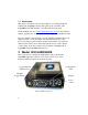
2.1 Front panel controls The Power button and Power LED are located in the upper left corner of the front panel. When the power is turned on, the LED will flash green and red while the system runs its initial tests, and turn green when the tests have passed. Site-Light These buttons toggle between SITE mode and LIGHT mode. When the SITE button is lit, the four storage buttons A D represent four different stored positions, and the keypad controls the traverse movements.
of the A D buttons. Keypad In SITE mode, the four buttons will move the traverse in the x and y directions. Pressing a button will start the traverse motor at low speed, and after about two seconds motor speed slowly ramp up to high speed. Pressing the button briefly allows single stepping of the traverse. Pressing the center button (Stop) will immediately stop any traverse movement which may be in progress.
2.2 Back panel connections The Model 1420 back panel 2.2.1 Video output The video signal is output on two connectors: a BNC connector with composite, analog RS170 or NTSC video, and an S-video output compatible with most video cards and analog recorders. It is generally recommended to use the S-video for best image quality, but some monitors without S-video input may require the composite video signal. The supplied Hauppauge WinTV card has both S-video and composite input connectors. 2.2.
Pin connections 1 5 V DC (max 3 A) 2 Chassis Ground (0 V) 3 Chassis Ground 4 Chassis Ground 5 Chassis Ground 6 LED A drive (TTL) 7 LED B drive (TTL) 8 LED C drive (TTL) 9 LED D drive (TTL) The light intensity of the LED s of the Model 1420 is controlled by pulse width modulation with a frequency synchronized to the video signal. Full light intensity means an illumination duty cycle close to 100%. LED drive outputs A D are negative logic, ie. TTL level is high when LEDs are off. 2.2.
Removing the microscope stage 2.4 Camera module The camera module is attached to the traverse by magnetic holders and can be removed by tilting the Model 1420 on its side and gently pulling the camera module down from below the Model 1420 body until it comes free. Important! Before removing or inserting a camera, turn off the Model 1420 using the power button at the left of the front panel.
Camera module Note: When removing or inserting the camera module, take care not to apply excessive force since this may damage the traverse mechanism and compromise traverse accuracy. 2.5 Microscope objective The microscope objective is a standard DIN type objective with 160 mm conjugate image distance. To replace the objective, remove the camera module and unscrew the objective. The Model 1420 supports objectives with magnifications from 4× to 20×.
Objective and seat for fluorescence filter 2.6 Fluorescence filter The fluorescence filter is located in the objective mounting ring right behind the microscope objective and can be replaced by unscrewing the objective. The filter size is half inch (12.7 mm) diameter, and the filter fits into a recess in the microscope mounting ring. 2.
Removing the illumination module Note: When reinserting the illuminator module take care that the connector pins are all correctly inserted in the receptacle without bending or damaging the pins. Also take care not to apply excessive force. Support the camera module from below with your hand when inserting the illumination module and press from below to ensure the traverse mechanism is magnetically seated. 2.8 Base stand The Model 1420 is delivered with four rubber feet attached with 8-32 screws on a 7.
3 VIDEO AND ILLUMINATION TIMING The master clock for the Model 1420 is provided by the video signal timing. The CCD camera outputs video in standard RS170 format (NTSC in the color version), which is an analog, interlaced format compatible with standard analog video monitors or video recorders.
4 scopePRO SOFTWARE The scopePRO software lets you set the functions of the Model 1420 and control the video acquisition and on-line processing. It also allows you to recall and process stored video files. scopePRO runs on any PC with Microsoft Windows XP operating system. Note The scopePRO application makes extensive use of the DirectX software, which is provided by Microsoft Corp. and installed independently of scopePRO.
Probe controls Presets panel LED control panel Focus control Traverse control Video display window Video recording panel scopePRO main window The video display window shows the off-line or on-line (live) video as selected in the Video menu. The position indicators to the right and below the video display indicate the position of the x-y traverse and can be used to move the traverse. The traverse can also be activated by the keyboard up and down arrow keys.
The LED control panel slider bars are used to adjust the intensity of the four LED banks, A D. The LED intensity is adjusted by pulse width modulation with a fixed pulse frequency that is synchronized to the video field frequency. Checking the Gang box will cause all LED banks to be adjusted simultaneously when one slider is activated. The focus control panel is used for moving the focus actuator up and down. The + and buttons move the actuator in single steps.
4.3 Upgrading firmware The firmware is the software stored inside the Model 1420 in non-volatile memory and controls the internal functions of the instrument, such as traverse movements, front panel lamps and buttons, and back-panels inputs and outputs. The firmware is included in the scopePRO application package and can be loaded into the Model 1420 from within the scopePRO software. To upgrade firmware to the latest version: 1. Download the newest version of scopePRO from www.berkeleynucleonics.
5 RUNNING THE scopePRO SOFTWARE When you run the scopePRO application, it will automatically connect to the Model 1420 if it is present on a serial port and turned on. If scopePRO does not find a Model 1420, the communications settings box will appear as shown above. Select the correct serial port and press OK. The scopePRO main window below will appear. For off-line mode, open the AVI file you want to process off-line. The Model 1420 does not have to be connected.
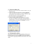
Video options menu Click on the video capture card that you want to use. Select the appropriate capture source. Make sure that either the BNC composite or S-Video connector output of the Model 1420 is connected to an input of the Hauppauge card, and select the relevant input connector through the Input connector box. Click View>Video options>Input connector and select the input that you want (e.g. Input: 0: Video SVideo In, Output: 0: Video Decoder Out). Click OK.
Input connector selection box. You do not have to worry about the audio options since they are not currently used for the scopePRO application. To set the video frame size you can click Video>Video options>Video frame format. Select 320×240 for low-resolution images and 640×480 for full-resolution images. Do not change the color space (whatever comes up, normally RGB24, is correct). Note: The DirectX video controls dialog boxes are of general nature and allow settings incompatible with the Model 1420.
Look Up Tables (LUT s), which convert the analog voltage outputs of the video signal to the appropriate gray scale or color values. If you have a B&W camera, you want to make sure you are using an 8-bit LUT, converting the analog voltage into 256 different gray scale levels. Normally you would use a grayscale LUT, mapping the 256 gray scale levels into 256 different shades of gray, but you can apply color LUT s for false color display.
6.1 Video compression Video compression algorithms like MPEG are great for normal TV recording, but may not work properly when used for scientific video sequences, which often obey completely different statistics. MPEG video compression is particularly bad for video sequences containing small, rapidly moving objects, which is exactly the kind of imagery likely in microfluidics experiments.
Camera A/D converter Video display Hard disk RAM buffer Buffering scheme in scopePRO The analog video signal from the Model 1420 camera is digitized in the Hauppauge WinTV card into an 8 bit data stream. This stream is continually stored in a cyclic RAM buffer in PC memory, such that the most recent video data is always residing in RAM.
Setting of RAM and disk buffer size The disk buffer is a contiguous area on the system disk set aside for storing the video sequence in AVI format. The buffer settings dialogue box allows you to specify the name and size of the disk buffer. Once the disk buffer runs full during a recording session, the file system will start to allocate extra disk space to hold the new data as is comes in. This will considerably slow down the effective disk writing speed, resulting in dropped frames.
Trigger Stored video Time RAM Buffer Stored video Time Disk Buffer Pre-trigger (top) and post-trigger (bottom) recording For pre-trigger recording, you save the video sequence occurring before the trigger, stored in the RAM buffer. With post-trigger recording you save the video sequence occurring immediately after the trigger and temporarily stored in the disk buffer. The disk buffer is normally larger than the RAM buffer. 6.
6.6 Deinterlacing The camera built into the Model 1420 runs in standard RS-170 (monochrome) or NTSC (color) video format at a fundamental frame rate of 30 Hz. As discussed in section 5.1, the full video frame is composed of two interlaced fields at a field frequency of 60 Hz. This means that every second line of a full image is recorded at a time 16.6 ms later than the other half of the lines.
Selecting deinterlace filter The best deinterlace filter depends on the nature of the video image and should be chosen by experimentation. A brief description of the four algorithms is given here. For more information, see the home page of the developers, listed in the dialog box. Weave This method uses three fields in the calculation and works well on slow moving material but tends to fail on fast moving material.
Although the deinterlace filters improve the visual appearance of the video, they are designed for general video scenery and may not be effective for scientific imagery. All filters are based on some form of interpolation between frames under the assumption that scene motion is continuous between frames. When the movies are analyzed by various algorithms, the effect of the deinterlace filter on the result will be algorithm-dependent.
Alternately, you can also open an existing flow movie by choosing Video > Process Saved Video. The video will loop until stopped. 7.3 Creating probes To create a probe: 1. 2. Click the PIV toolbar button . Double-click in the video image at the center point for the new probe. When you create a probe it will take on the properties of the last probe you altered. Once created you can change each probe s properties individually.
these locations even if you make the probes completely invisible. 4. To remove a probe, right click on it and choose Delete. 7.4 Probe Properties 1. Double-click on a probe to open the PIV Probe Properties dialog box. You can also right-click on the probe and choose Properties to open the dialog box. PIV Probe Properties dialog box. 2. 34 Select the Width and Height of the probe window, the area over which statistics will be calculated. Some guidelines for setting the probe window size are: a.
d. If the probe is located in a region of fast flow, the probe size must be large enough that the correlation does not fall beyond the window. The Cross Correlation field (see below) can be an aid in setting the size. NOTE: If you cannot achieve sufficient signal-to-noise ratio with a required probe size you may need to adjust the illumination, particle feed, etc. If the probe is in an area of steady flow then increasing time averaging may also help. 3.
NOTE: If the probe is located in an area of very slow flow then subtracting the background could delete active particles. c. Deconvolve Autocorrelation is an advanced option for high precision measurements. This option deconvolves the cross correlation by the autocorrelation, which can remove the effects of blur and particle size such that each particle is treated as a single point. It is most useful when the signalto-noise ratio is extremely high. 5.
7.5 Recording Data Data can be recorded simultaneously from all probes. To record data: 1. Choose File >Measurement File Naming to select how the recorded data will be save: Naming settings for new measurements dialog box. a. If you choose Do not auto-name, scopePRO will prompt you for a file name and location for each new recording. b. Choose Auto-name files to automatically name each recording. Check Append the date, Append the time, and/or Append counter to add these values to the new file names.
The PIV output file will include four columns for each probe: the X and Y locations of its centroid, measured from the upper left of the window, and the X and Y velocity at each point in time. The X/Y location columns will only have entries in the first row. 7.6 Saving Probes A set of probes can be saved to disk and recalled later: 1. Arrange the probes and set their Properties. 2. Choose File >Save Probes As to create a new probe file. 3. Select the name and location for the file and click Save.
8 SPECIFICATIONS Traverse Range Resolution x: 50mm, y: 75 mm, focus: 8mm x and y: 10 µm, focus (z): 1 µm Sample stage Dimensions Opening X × Y: 140mm × 200mm 55 × 80 mm Camera module RS-170-BW RS-170-C Objectives Illuminator modules Inputs Outputs Communication interface Analog, interlaced monochrome camera with 1/3 CCD 640 × 480 pixels, 30 frames/s Bayer-pattern analog color camera with 1/3 CCD 640 × 480 pixels, 30 frames/s 10× plan 0.
Physical Dimensions Weight Power requirement 40 W × L × H: 208 × 267 × 85 mm 2.