621M OPERATING MANUAL 1621M OPERATING MANUAL hospitals • nuclear power plants • labs • H A Z M AT • waste processing palmRAD Model 1621M
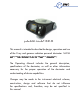
palmRAD Model 1621M • This manual is intended to describe the design, operation and use of the X-ray and gamma radiation personal dosimeter 1621M (hereinafter referred to as the device or dosimeter). hospitals • nuclear power plants • labs • HAZMAT • waste processing The Operating Manual includes the general description, specifications of the dosimeter, as well as other information necessary for the proper operation of the dosimeter and understanding of device capabilities.
1621M OPERATING MANUAL DESCRIPTION & OPERATION OF THE DOSIMETER 1.
Dosimeters may be used independently or as a part of a system for everyday, efficient and emergency dosimetric control of personnel, production facilities and units where there is a potential or real risk of exposure to external X-ray and gamma radiation.
1621M OPERATING MANUAL INSTRUMENT SPECIFICATIONS: Detector Geiger-Muller tube Dose equivalent rate measurement range (DER) Hp(10) 10 µR/hr - 100 R/hr (0.1 µSv/hr - 1 Sv/hr) Energy range 10 keV - 20 MeV Energy response relative to 0,662 MeV (Cs-137) within the full energy range ±30% Drop test on concrete floor 0.
1.4 Design and theory of operation 1.4.1 The dosimeter is comprised of the following main blocks and modules: radiation detector; microprocessor; LCD; secondary power supply; IR-transceiver; and non-volatile memory. Figure 1.
1621M OPERATING MANUAL 1.4.2 The device is housed in a plastic shock-proof case. A general overview of the dosimeter and its parts is shown in Figure 1.2. Features numbered 1-4 on the figure are located on the LCD panel (8). Figure 1.
1. DER analog scale (seven segments) for quick visual status of radiation situation; 2. DER digital panel in DER indication mode, DE in DE indication mode, year of production in number indication mode, IR communication channel on/off indication in the PC communication mode. 3. Coefficient of variation indication in percents in DER indication mode, DE accumulation time s in thousands of hours (h) in DE indication mode, month of production in the dosimeter s number indication mode; 4.
1621M OPERATING MANUAL The dosimeter’s operating algorithm ensures continuity of the measurement process, statistical processing of the measurement results, a prompt adaptation to the variation of level of the photon radiation dose rate (setting the time of measurement in inverse dependence on the dose rate) and effective output of information to the LCD. The IR-communication channel allows an exchange of information with a PC.
2 USE OF THE DOSIMETER 2.1 General Guidelines When you receive the device after purchase please check the delivery kit and confirm proper operation of the device in all the operation modes as outlined in sections 2.4.3 to 2.4.5. Protect the device from shocks and mechanical damage. Avoid exposing the device to hostile environments, organic solvents and open fire. 2.
1621M OPERATING MANUAL 2.4 Use of the Dosimeter 2.4.1 The dosimeter operates in the following modes: • Photon radiation DER indication mode; • Photon radiation DE indication mode; • Number indication mode (“blind dosimeter”); • Mode of data transmission to PC; • Set mode; • Partial or critical battery discharge indication mode; • Audible alarm mode when exceeding preset DE or DER thresholds.
Standard configuration of the dosimeter as shipped includes the following parameters and functions: DER Indication Mode - On Figure 1.2, Item 2 Figure 1.2, Item 3 Figure 1.2, Item 4 Thresholds setting enable: Audible alarm: DER values output output of the coefficient of variation values - Off output of DER values averaging - Off Off Off DE Indication Mode - On Figure 1.2, Item 2 Figure 1.2, Item 3 Figure 1.2, Item 4 Figure 1.
1621M OPERATING MANUAL 2.4.2 Selection of an Indicated Parameter DER, DE, dosimeter’s number and data transmission to PC modes are switched on by a successive pressing of the MODE button (Figure 2.1, Item 6). The dosimeter allows for switching all the above-mentioned indication modes on and off. Change of the configuration is performed in data transmission to PC mode. 12 Figure 2.
2.4.3 DER Indication Mode In the DER mode (Figure 2.1) the following values appear on the LCD: • DER (µR/h, mR/h, R/h); • DER on the analog scale in a logarithmic gauge (seven segments); • Coefficient of variation in percents; • Averaging time of DER values (Range of the averaging time indication is from 1 up to 2999 s. If the averaging time exceeds 2999 s, the symbols - - - appear on the LCD).
1621M OPERATING MANUAL The second method. The dose value in the beginning of the period of measurement should be deducted from the DE value displayed at the end of the period. In the DE mode the indication (Figure 1.2, items 3 and 4) of values of time remaining for staying at the working place depending on the current measured DER and DE values is possible. Calculation of time is performed relative to the second preset DE threshold (the function may be switched on at the DE indication mode configuration).
2.4.5 Set mode Auxiliary set mode (Figures 2.2 and 2.3) is meant for verification and (or) setting of the threshold DE (DER) values, DE and DE accumulation time reset. Attention! To enter the “set” mode press and hold the LIGHT/SET button for about 5 seconds until the parameter to be set is flashing. To choose the parameter, press and release the LIGHT/SET button. Press and hold the MODE button to rapidly change the parameter. Press and release the MODE button to change the parameter to an exact setting.
1621M OPERATING MANUAL 2.4.6 Number Indication Mode In number indication mode, the following items appear on the LCD: • The dosimeter’s number on a display (Figure 2.1, Item 2); • Year (Figure 2.1, Item 4) and month (Figure 2.1, Item 3) of production. 2.4.
To use the dosimeter in data transmission to PC mode: • Read and follow the recommendations of the file Read_me.doc on the CD supplied with IR adapter; • Read the help file Help_ 1621.doc; • Connect the adapter of IR communication channel to a PC COM port; • Install the IrDA communication unit and switch on the IR connection; • Install the program “System of Data Collection and Processing for the 1621/ 1603/1604 Devices” from the CD, (run the program \DISK1\SETUP.EXE); • Run the program 16XX.
1621M OPERATING MANUAL 2. Read-out of the following information from dosimeter to PC: • Dosimeter’s parameters; • DER history and DE accumulation (date, time, event, value); • DE (DER) values at the moment of exceeding the preset thresholds as well as time, date and month of exceeding the preset thresholds; • Values of the preset DE and DER thresholds; • Official information 3.
Figure 2.
1621M OPERATING MANUAL 3. MAINTENANCE 3.1 Maintenance involves preventive services, battery replacement and a regular performance check (according to 2.4.3 - 2.4.5). 3.2 Preventive services include external examination, dusting and decontamination in the event of radioactive contamination. For decontamination wipe the case of the dosimeter using a cloth wetted with ethanol. 3.
4. TROUBLESHOOTING The list of possible problems and their solutions are specified in Table 4.1 Problem Possible Cause Solution The LCD indicates “bAt” message Battery discharge Replace Battery No indictions on LCD Battery discharge Battery inserted incorrectly Replace Battery Insert battery correctly The device does not respond to pressing a button.
1621M OPERATING MANUAL 6. WARRANTY 6.1. Berkeley Nucleonics Corporation warrants all instruments, including component parts, to be free from defects in material and workmanship, under normal use and service for a period of one year. If repairs are required during the warranty period, contact the factory for component replacement or shipping instructions. Include serial number of the instrument.
23
1621M OPERATING MANUAL 24
Anisotropy of the device for each energy does not exceed values (in %) presented in Table 1.1, when the device is rotated in the horizontal plane (Appendix B, Figure B.1) and values (in %) presented in Table 1.2, when the device is rotated in the vertical plane (Appendix B, Figure B.2). Table 1.1 Angle of the detection relative to the direction of the graduation 0 15 30 45 60 -15 -30 -45 -60 Energy of gamma radiation MeV Anisotropy 0.059 0 ±5 ±10 ±20 ±40 ±5 ±10 ±20 ±40 0.
1621M OPERATING MANUAL 2955 KERNER BLVD. SAN RAFAEL, CA 94901 • TEL 415.453.9955 • FAX 415.453.9956 I N F O @ B E R K E L E Y N U C L E O N I C S . C O M • W W W. B E R K E L E Y N U C L E O N I C S .