
Owner manual

20
OPERATING INFORMATION
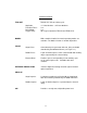
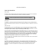
Control Keypad
Some of these keys are dependent on the presence of a plug-in module. For example, the LEVEL,
STORE and RECALL keys function only with a module installed. The keys on the control keypad can
be divided into the following subsets: menu key, memory keys, function keys, and scan keys, as well as
the LOCAL and UNITS keys.
The five menu keys. MODE, TRIG. TIMING, LEVEL, and GPIB/RS-232, step through a number
of possible states or parameter displays, allowing the user to configure the instrument's operating
characteristics. The memory keys, STORE and RECALL, allow storage and retrieval of ten complete
instrument settings. The function keys are reserved for use with future modules. The scan keys, {}
{}, {}and () are used to modify parameters that have been previously entered.
The two remaining keys do not fall into any of the above categories. The LOCAL key returns instrument
control to the front panel from either GPIB or RS-232. The UNITS key allows the user to select between
different display units for the level parameter (an optical unit, for example, may allow the display of the
level settings in units of either Watts or dBm).
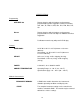
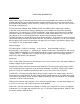
Numeric Keypad
The right keypad is similar to a calculator. It has keys for the decimal digits (0-9), the
decimal point (.), sign change (+/-), exponent (10
x
), backspace (BK SPC), enter (ENTER), and execute
(EXEC). ENTER and EXEC are used to terminate data entry and also to trigger a Single Cycle timing
sequence. The {+/-, SGL/DBL} key is used both to indicate negative values and to toggle between
Single Pulse and Double Pulse operation.
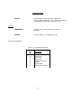
Connectors
There are three BNC connectors on the front panel. These are used in the Pulse and Impulse Modes to
monitor or trigger the pulse generator.
PULSE OUT provides waveform synchronized to TRIG OUT. The time position (with respect to TRIG
OUT) and duration of this output are set by the Delay and Width, respectively. PULSE OUT produces
pulses of a fixed +5 V amplitude (into 50 ohms) with 1 ns rise times and an 1.5 ns fall times.
PULSE OUT is nominally coincident with the plug-in module's output. The "module delay" (the fixed
time between the mainframe PULSE OUT and the module output) depends on the module being used
and is given in the module manual. In Impulse Mode, PULSE OUT has a fixed width of 5 ns (the Width
setting has no effect in Impulse Mode).
TRIG IN is the input for external triggers. It has a 50 ohm input impedance, can take input voltages up
to ±7 V dc or 7 V ac pk, and accepts frequencies up to 100 MHz.
TRIG OUT is the lime marker for the beginning of a timing cycle. TRIG OUT has fixed +3 V amplitude
(into 50 ohms), a 3 ns width, and transition times of 3 ns. In External Trigger operation, TRIG OUT will
occur 20 ns after the TRIG IN signal.