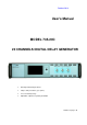
October 2014 User's Manual MODEL 745-20C 20 CHANNELS DIGITAL DELAY GENERATOR 20 independent delay channels 100 ps delay resolution (1 ps option) 10 seconds delay range Adjustable output level, polarity and width Number of pages: 30
User's Manual - MOD745-20 October 2014 TABLE OF CONTENTS EDITION ........................................................................................................................................................................... 4 1. GENERAL INFORMATION .................................................................................................................................. 5 1.1. 1.2. OVERVIEW ..............................................................................................
User's Manual - MOD745-20 October 2014 6.2.11. IP adress ................................................................................................................................................... 25 6.2.12. Netmask adress.......................................................................................................................................... 25 6.2.13. Gateway adress ...................................................................................................................
User's Manual - MOD745-20 October 2014 Edition Written by : Date & Visa : D.
User's Manual - MOD745-20 1. October 2014 GENERAL INFORMATION 1.1. Overview The MOD745-20 Digital Delay Generator provides twenty independent delayed output pulses. Delays up to 10 seconds may be programmed with 100ps resolution (1ps optional) and a channel to channel jitter of less than 50 ps RMS. BNC outputs deliver delayed pulses with adjustable level (3 to 6V) and width into 50Ω load. A polarity control allows to have inverted pulses.
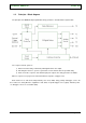
User's Manual - MOD745-20 1.2. October 2014 Principle – Block diagram The principle of the MOD745-20 programmable delay generator is described in the figure bellow. The sequence follows 3 phases: 1) After an insertion delay, a reference pulse appear at the “T0” output, 2) Following the reference, a pulse is generated on each channel after the specified delay, 3) At the end of the sequence, after last delayed pulse outputs, the delay generators are initiate.
User's Manual - MOD745-20 2. October 2014 SPECIFICATIONS Delays Channels 20 independent delay channels Range 0 to 10 seconds Resolution 100 ps (1 ps option) RMS Jitter < 50 ps + delay x 10 rms -7 Internal time base Frequency CLK RF Stability 10 -8 Trigger Single shot source SS1 and SS2 SS1 synchronous with the first occurrence of F3 and SS2 with the second occurrence of F3.
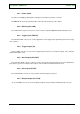
User's Manual - MOD745-20 3. October 2014 INSTALLATION 3.1.1. Power source The MOD745-20 can be operated from 90 VAC to 240 VAC nominal supply source. The maximum power consumption of the MOD745-20 is 80 W. 3.1.2. Power cord The MOD745-20 comes with a removable power cord for US operation. It has a three contact plug for connection to both the power source and protective ground. 3.2.
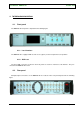
User's Manual - MOD745-20 4. October 2014 INTERFACES DESCRIPTION 4.1. Front panel The MOD745-20 front panel is depicted in the following figure. 4.1.1. Local interface The MOD745-20 is equipped with a touch screen (option) on the front panel for local operation. 4.1.2. AUX 1 to 3 The three BNC connectors located on the front panel are used for extension to 40 channels. They are unused in the MOD745-20 version. 4.2.
User's Manual - MOD745-20 October 2014 4.2.1. Power switch The unit is turned ON by switching the red button located above the mains connector. The MOD745-20 can be operated from 90 to 240 V at a line frequency of 50 – 60 Hz. 4.2.2. Ethernet port (LAN) The “LAN” RJ45 rear panel connector is used to remote control the MOD745-20 with TCP/IP protocol. 4.2.3. Trigger input (TRIG IN) The “TRIG IN” BNC connector is used for application of the trigger input signal that generates the single shot sequence. 4.2.
User's Manual - MOD745-20 October 2014 LOCAL OPERATION 5. 5.1. Main menu After power on, the main menu appears on the touch screen as depicted below. PULSE OUTPUT displays the settings of each channel T0 to T20. INTERNAL FREQUENCIES displays the actual set of frequencies F1, F2 and F3. STATUS displays the status of the equipment (internal or external clock and status). 1 to 20 indicators light up in green when the corresponding channel has been triggered. TRIG runs a unique single shot sequence.
User's Manual - MOD745-20 5.2. October 2014 Sub-menu “PULSE SETUP OUTPUT” Tapping in the “PULSE OUTPUT” window on the main menu will open a sub-menu with the channel settings depicted in the following figure. DELAY parameter is the delay of the channel, relative to T0, in ps. AMPLITUDE parameter is the voltage level of the channel, in mV. WIDTH parameter is the width of the channel, in ns. POLARITY parameter is the quiescent level of the channel. TRIGGER parameter is the trigger source of the channel.
User's Manual - MOD745-20 October 2014 Positive : quiescent level of the channel is 0V POLARITY Negative : quiescent level of the channel is at amplitude level T1 to T20 DELAY 0 to 9 999 999 999 999 ps in 100 ps steps or 1 ps steps (option) The default values of the equipment are the following: IP ADRESS : 99.0.0.18 GATEWAY ADRESS : 99.0.0.01 NET MASK : 255.0.0.0 F1 : 1000 Hz F2 : 100 Hz F3 : 10 Hz Level: 5.
User's Manual - MOD745-20 5.1. October 2014 Sub-menu “Delay” Tapping in the “DELAY” window on the “PULSE SETUP OUTPUT” sub-menu will open another sub-menu with the delay settings of the channel depicted in the following figure. To set the channel delay, enter the value with the numbers, then tapping on the unit (ps, ns, µs, ms or s) will validate the setting. Erase Exit sub-menu Note: Out of range values are rejected. 5.2.
User's Manual - MOD745-20 5.3. October 2014 Sub-menu “Width” Tapping in the “WIDTH” window on the “PULSE SETUP OUTPUT” sub-menu will open another sub-menu with the width settings of the channel depicted in the following figure. To set the channel width, enter the value with the numbers in nanoseconds, then tapping on the validate button will send the setting. Erase Exit sub-menu Validate Note: Out of range values are rejected. 5.4.
User's Manual - MOD745-20 5.5. October 2014 Sub-menu “Frequency” Tapping in the “F1”, “F2” or “F3” window on the “INTERNAL FREQUENCIES SETUP” sub-menu will open another sub-menu with the corresponding frequency settings depicted in the following figure. To set the frequency, enter the value with the numbers, then tapping on the unit (Hz or KHz) validate the setting. Erase Exit sub-menu Notes: - Out of range values are rejected. The frequency values can be set in a 1 – 2 – 5 sequence.
User's Manual - MOD745-20 5.7. October 2014 Sub-menu “IP Address” Tapping in the “IP Address” window in the “NETWORK ADDRESS SETUP” sub-menu will open another sub-menu with the IP address setup as depicted in the following figure. Erase Exit sub-menu Validate Notes: Submenus “NETWORK MASK” and “GATEWAY ADDRESS” are identical. 5.8.
User's Manual - MOD745-20 6. October 2014 REMOTE CONTROL 6.1. Connection To connect over the LAN, follow these steps: Connect the instrument LAN connector to the remote control computer, On the user interface, either specify the LAN address, On the remote controlcomputer, enter the instrument’s IP address, After the connection has been established, the following commands can be used to modify the settings: 6.2. o Set the instrument’s IP address with: IP XXX.XXX.XXX.
User's Manual - MOD745-20 October 2014 6.2.1. IDENTIFICATION Syntax: *IDN? Form: Query Description: Query instrument identification. Response gives instrument model, serial number and firmware version. Parameter: - RST value: - Example: Answer: GFTy/MIPSI,MOD745-20,SN54001/000000,V1.0 Instrument model: MOD745-20 Serial number: 54001 Firmware version: 1.0 6.2.2.
User's Manual - MOD745-20 October 2014 6.2.3.
User's Manual - MOD745-20 October 2014 6.2.5. WIDTH Syntax: WIDTH T, WIDTH? T Form: Set & Query Description: Query channel width or set channel at specified width Parameter: : Channel number (0 to 20) : Width (in nanosecond) RST value: Last value set Range: 100 to 300 000 000 ns Example: Set 250 ns width on channel 4: WIDTH T4,250 Query width of channel 4: WIDTH? T4 (Answer: :WIDTH T4,2500) 6.2.6.
User's Manual - MOD745-20 October 2014 6.2.7. FREQUENCIES Syntax: FREQ F, FREQ? F Form: Set & Query Description: Query frequency of internal Frequency or set frequency of internal Frequency Parameter: : 1, 2 or 3 (Frequency 1, Frequency 2 or Frequency 3) : Frequency (in Hertz) RST value: Last value set Range: 0.1 to 1 000 Hz (in 1, 2, 5 sequence) Example: Set internal Frequency 3 to 0.5 Hz: FREQ F3,0.
User's Manual - MOD745-20 October 2014 6.2.9.
User's Manual - MOD745-20 October 2014 6.2.10. STAT Syntax: STAT CLEAR STAT? Form: Set & Query Description: Query equipment information Parameter: : TEMP (Temperature in °C) CLK (Clock source, internal or external) POW (+6V, -6V, +3.3V, +1.8V, +11V power supply level in V) TRIG (Trigger feedback for channel 1 to 20. 1 = trigged) MTRIG (Single shot trigger feedback. 1 = trigged) RST value: - Example: Clear information: STAT CLEAR Query temperature: STAT? TEMP (Answer: :STAT TRET,28.
User's Manual - MOD745-20 October 2014 6.2.11. IP adress Syntax: IP IP? Form: Set & Query Description: Query IP Address or set it Parameter: : IP address RST value: Last value set Example: Set IP address to 172.17.23.6: IP 172.17.23.6 Query IP address: IP? (Answer: :IP 172.17.23.6) 6.2.12. Netmask adress Syntax: NM NM? Form: Set & Query Description: Query Netmask Address or set it Parameter:
User's Manual - MOD745-20 October 2014 6.2.13. Gateway adress Syntax: GW GW? Form: Set & Query Description: Query Gateway Address or set it Parameter: : GW address RST value: Last value set Example: Set Gateway address to 172.17.23.7: GW 172.17.23.7 Query Gateway address: GW? (Answer: :GW 172.17.23.
User's Manual - MOD745-20 6.3.
User's Manual - MOD745-20 October 2014 The “SYNC MESSAGE” area allows to: - Change the values of F1 to F3 Toggle between Run and Stop states (“Run” button lights green when in “Run” state) Perform a single shot (“Trigger” button lights green when a single shot occurred, and can be erased by clicking on the state led of the channels) The “STATUS” area shows: - The level of the internal power supplies The internal temperature of the unit The state of the clock (lights in green when external clock) Notes
User's Manual - MOD745-20 7. October 2014 SOFTWARE The MOD745-20 comes with DLL drivers for Windows XP or Seven. Our primary objective in designing software drivers is to get the user up and running as quickly as possible. Software drivers are provides as a Dynamic Link Library (DLL) which is compatible with most 32-bit windows based development software. The main program is written on Labview v11 or later. The listing of files is the following: MOD745-20: main program, DLL or vi: o *.dll or *.
User's Manual - MOD745-20 October 2014 The Labview driver front panel is shown below : Page 30 / 30