
Manual
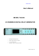


User's Manual - MOD745-20
October 2014
Page 6 / 30
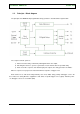
1.2. Principle – Block diagram
The principle of the MOD745-20 programmable delay generator is described in the figure bellow.
The sequence follows 3 phases:
1) After an insertion delay, a reference pulse appear at the “T0” output,
2) Following the reference, a pulse is generated on each channel after the specified delay,
3) At the end of the sequence, after last delayed pulse outputs, the delay generators are initiate.
When a sequence is in progress the instrument will not respond to a trigger event.
Each channel T1 to T20 can be independently set in level, width, delay, polarity and trigger source. All
these values are saving when the equipment is shut down, except the trigger source (option). After the power
on, all trigger sources are set to OFF (INH).