GEN 5 INTIMIDATOR VICE & PROTÉGÉ MANUAL VERSION 2.0 BOB LONG TECHNOLOGIES 209-293-4440 www.boblongdirect.
CONTENTS Contents ................................................................................................................................................................ 2 Warning ................................................................................................................................................................. 3 Warranty.......................................................................................................................................................
WARNING This paintball marker is not a toy. Misuse or mishandling can result in serious injury or death. Every person within range of a loaded paintball gun must wear eye protection specifically designed for paintball. It is recommended at least 18 years of age to purchase, 14 years old to use with adult supervision or 10 years old to use on paintball fields meeting ASTM standards F1777-97. Ensure you read the entire instruction manual before operating your marker.
QUICK START INSTALLING AIR TANK Much like any other tournament marker, the Vice requires the use of compressed air or nitrogen only. The Vice is compatible with both high-pressure and low pressure compressed air systems. If using an adjustable-output air system, set the system’s output between 450 and 550 psi. Screwing your preset air system into the ASA at the bottom of the grip will pressurize the marker, preparing it for use.
GENERATION 5 MODEL DIFFERENCES: The fifth generation Intimidator platform, including the Vice and Protégé, share the same basic operation and underlying technology. While the Protégé provides tournament level performance in a cost effective package, the Vice brings a fully loaded marker that is lighter and fully equipped. Both are designed, machined, and built in the USA. Vice Feedneck Control Board Bolt Weight Ram Sleeve LeverLock Tadao Ryujin Pillow Bolt Lighter Integrated Protege Twist Lock Frenzy 4.
ADJUSTING THE TRIGGER The Gen 5 Intimidator trigger has two adjustment screws. The bottom screw is for trigger post-travel and the top screw adjusts the activation point (where the marker fires). To adjust the screws insert a hex key and turn the screw. The screws have Loctite to prevent the adjustment from slipping so a firm, steady pressure is needed for the adjustment. REPLACING/UPGRADING The stock trigger is similar to the S-class trigger. However, the stock trigger does not have a roller bearing.
ADJUSTING THE ASA (FRONT/BACK) The Air Source Adapter (ASA) that connects your high pressure air tank to your Vice is a direct mount ASA. Direct mount ASA systems have screws that attach directly to the bottom of the grip frame. This ASA can be adjusted forward or backwards to help position the tank so that it is comfortable for you. 1. Loosen the four set screws in the ASA then lower it from the mounting studs. Notice the smiley face integrated into the milling? Pretty cool, eh? 2.
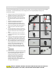
MAINTAINING THE EYES AND DETENTS In the event of a chopped ball or debris in the breach, your marker eyes may need cleaning. 1. 2. 3. 4. 5. 6. 7. Remove the eye cover screw using a 5/64” hex wrench, and remove the eye cover. Carefully unscrew the PCB retaining screw. (Phillips head) Remove the detent and spring by pressing on the detent from inside the chamber. Gently tilt the eye PCB away from the body of the marker in order to access the inside surface.
MAINTAINING THE HPR Your Vice comes equipped with the best regulators on the market. To ensure the best consistency and the highest flow possible, it is recommended that you clean and grease the in line regulator (HPR) according to the maintenance schedule. 1. 2. 3. 4. 5. 6. 7. 8. 9. Degas the marker and ensure that there are no paintballs in the breech or barrel of the marker. Remove your macroline hose from the 90˚ fitting on your regulator.
SETTING HPR PRESSURE The HPR pressure is adjusted through a hex screw at the bottom of the regulator. Turning the screw clockwise increases the pressure and velocity. Turning it counterclockwise will lower the pressure and velocity. Only turn the wrench 1/8th -1/16th of a turn with each adjustment. After rebuilding the regulator you can do a basic setting using a second ASA with a gauge installed in the place of a macro fitting.
MAINTAINING THE LPR 1. 2. 3. 4. 5. 6. 7. 8. 9. Remove the macro-line and the HPR from your marker. Set the regulator to the side. Remove the LPR retaining screw from inside the vertical adaptor. Slide the LPR assembly forward and out of the marker Remove the adjustment screw from the end of the LPR then remove the LPR cap. Tap the LPR body on a hard, flat surface to allow the LPR piston, spring, and spring follower to slide out of the regulator base.
MAINTAINING THE POPPET VALVE ASSEMBLY 1. 2. 3. 4. 5. With the LPR removed from the marker, remove the poppet valve by tapping the front of the marker firmly against the palm of your hand or a padded surface. Alternately use a pair of needle nose pliers, remove the poppet return spring and poppet valve from the front of the ram sleeve.
MAINTAINING THE BOLT 1. 2. 3. 4. 5. 6. 7. De-gas the marker and insure that there are no paintballs in the breech or barrel of the marker. Remove the bolt from the marker by pulling upward on the pull pin. Slide the bolt to the rear of the marker body. Inspect the surface of the bolt and o-rings for excessive wear or nicks, and replace as necessary. Place one drop of oil on each o-ring and spread it around the ring with your finger to ensure an equal coating.
O-RINGS AND FASTENERS O-RINGS Part Name Specifications Quantity Drive Manifold O-rings 90 Degree Hose Barb Fitting Seal Solenoid Manifold O-ring Ram Cap (Vice – located on Ram Cap) Ram Cap (Protégé-located in Ram Sleeve) Poppet Shaft O-ring Front Ram O-ring Rear Ram O-ring LPR Piston O-ring Bolt O-rings 360˚ Regulator ASA Adapter Internal ORings 360˚ Regulator ASA O-ring Poppet Housing (Vice) Ram Sleeve (Protégé) 1mm X 3mm Buna (Durometer 70) 1mm X 3mm Buna (Durometer 70) 1mm X 4.
FASTENERS Part Name Specifications Quantity Bottom PCB Retaining Screw Top PCB to Grip Frame Bottom Air Passage Plug Rear Air Passage Plug (Vice) Front Air Passage Plug (Vice) Rear Air Passage Plug (Protégé) Front Air Passage Plug (Protégé) Eye Cover Screws Eye PCB Retaining Screws Drive Manifold Screw Trigger Activation Point Set Screw Trigger Post-Travel Set Screw Grip Panel Screws Xpress Mount ASA Set Screws Rear Grip Frame Screw LPR Retaining Screw 360˚ HPR Swivel Lock Screws 360˚ HPR Adjustment Scr
O-Ring Size Table 1x3mm 1x4.5mm 1x12mm 1x14mm 006 011 012 014 015 016 028 CAUTION: READ ALL WARNINGS BEFORE USING OR ATTEMPTING ANY WORK ON YOUR VICE. SHOULD YOU BE UNSURE AT ANY POINT, STOP AND SEEK PROFESSIONAL SUPPORT.
Q&A 1. Q: My Vice is VERY bouncy and I can’t do anything! I’ve topped out the debounce and AMB and I put the trigger in like every position possible. Would it be the loader delay help any? What else should I do? A: Make sure the trigger spring is installed. Make sure the trigger activates near the end of the pull. If necessary back out the trigger activation set screw ½ turn. 2. Q: Where can I get an o-ring kit? A: Bob Long Technologies and authorized resellers have o-ring and parts kits available. 3.
11. Q: Should my air hose be squeezed between the solenoid and frame like in the picture below? A: This is normal and does not impact air flow. 12. Q: Is the Stock trigger a roller bearing? A: Nope 13. Q: What items are recommended to keep in my toolkit? A: Each of the following: • LPR tester • Dow 55 • Triflow oil • O-rings • Timmy hose for solenoid • One wooden chopstick (occasionally helpful for poppet or ram removal) • Hex key set 14.
18. Q: What is the racetrack o-ring? A: It is the o-ring in the body of the marker above the grip frame. It is actually a round o-ring just sitting in the oval groove. If you have leaking between the body and grip frame remove o-ring, lubricate and place back into the slot. 19. Q: Where can I find additional information and other users of Bob Long Markers? A: www.intimidatorowners.com also the PBNation subforums dedicated to Bob Long products located at http://www.pbnation.com/forumdisplay.php?f=146 20.
TROUBLESHOOTING GUIDE Marker will not turn on out of the box Velocity is inconsistent over the chronograph Marker is breaking paint Marker does not gas up after tank is connected Marker does not display correct LED indicator color when turned on Marker is leaking from the ASA Marker is leaking from the HPR Air is leaking from the front of the marker frame -Ensure that the battery that you’re using in your new marker is a high quality alkaline 9 volt.
Air is leaking from the rear of the marker frame Marker leaks down the barrel Marker fires more than one shot per pull, or has trigger bounce Marker double feeds -Remove the trigger frame from the marker, and inspect the hose to the solenoid. If it appears worn or pinched, consider replacing the hose. -If your marker has this excessive compression of the hose replace the hose and apply a small amount of grease to the hose to allow it to compress in the frame without being deformed.