EN Operation & Maintenance Manual S/N 531711001 & Above EQUIPPED WITH BOBCAT INTERLOCK CONTROL SYSTEM (BICS) 6904144-EN (09-06) Printed in Europe © Bobcat Europe 2006
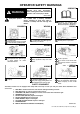
OPERATOR SAFETY WARNINGS CORRECT WARNING Operator must have instructions before running the machine. Untrained operators can cause injury or death. W-2001-1285 Safety Alert Symbol: This symbol with a warning statement, means: "Warning, be alert! Your safety is involved!" Carefully read the message that follows. CORRECT WRONG B-15570 B-15953 Always use the seat bar and fasten seat belt snugly. Always keep feet on the foot pedals or foot rest when operating loader.
FOREWORD CONTENTS FOREWORD ..............................................................................................III SAFETY .................................................................................................... XI SAFETY OPERATING INSTRUCTIONS....................................................................1 PREVENTIVE MAINTENANCE ................................................................61 SYSTEM SETUP & ANALYSIS ............................................................
T190 Compact Track Loader Operation & Maintenance Manual II
FOREWORD FOREWORD This Operation & Maintenance Manual was written to give the owner / operator instructions on the safe operation and maintenance of the Bobcat Loader. READ AND UNDERSTAND THIS OPERATION & MAINTENANCE MANUAL BEFORE OPERATING YOUR LOADER. If you have any questions, see your Bobcat dealer. BOBCAT COMPANY IS ISO 9001:2000 CERTIFIED................................. V DELIVERY REPORT .................................................................................
T190 Compact Track Loader Operation & Maintenance Manual IV
BOBCAT COMPANY IS ISO 9001:2000 CERTIFIED ISO 9001:2000 is an international standard that controls the processes and procedures which we use to design, develop, manufacture and distribute Bobcat products. British Standards Institute (BSI) is the Certified Registrar Bobcat Company chose to assess the Company’s compliance with the ISO 9001:2000 standard.
SERIAL NUMBER LOCATIONS Engine Serial Number Always use the serial number of the loader when requesting service information or when ordering parts. Early or later models (identification made by serial number) may use different parts, or it may be necessary to use a different procedure in doing a specific service operation. Figure 2 Figure 1 P-48002 The engine serial number is located on the side of the engine [Figure 2] above the oil filter.
LOADER IDENTIFICATION FRONT LIGHTS SEAT BAR OPERATOR SEAT WITH SEAT BELT GRAB HANDLES STEERING LEVER ▼ REAR AUXILIARY QUICK COUPLERS TILT CYLINDER STABILIZER ROD † BUCKET FRONT AUXILIARY QUICK COUPLERS BUCKET STEPS SAFETY TREAD ● OPERATOR CAB (ROPS & FOPS) REAR WINDOW LIFT ARM LINK REAR GRILL LIFT ARM LIFT CYLINDER TAIL LIGHT LIFT ARM SUPPORT DEVICE REAR LIGHT REAR DOOR TRACKS B-15984A B-15985A ▼ OPTIONAL OR FIELD ACCESSORY (Not Standard Equipment) † BUCKET - Several different buckets and other
FEATURES, ACCESSORIES AND ATTACHMENTS Standard Items Options and Accessories Model T190 Bobcat Loaders are equipped with the following standard items: Below is a list of some equipment available from your Bobcat Loader dealer as Dealer and / or Factory Installed Accessories and Factory Installed Options. See your Bobcat dealer for other available options, accessories and attachments.
Buckets Available FEATURES, ACCESSORIES AND ATTACHMENTS (CONT’D) These and other attachments are approved for use on this model loader. Do not use unapproved attachments. Attachments not manufactured by Bobcat may not be approved. The versatile Bobcat Loader quickly turns into a multi-job machine with a tight-fit attachment hook-up . . . from bucket to grapple to pallet fork to backhoe and a variety of other attachments.
Special Applications Kit Inspection And Maintenance FEATURES, ACCESSORIES AND ATTACHMENTS (CONT’D) • • • Special Applications Kit • • • • B-25286A Available for special applications to restrict material from entering cab openings. Kit includes 12 mm Lexan™ front door, top and rear windows. See your Bobcat dealer for availability. T190 Compact Track Loader Operation & Maintenance Manual X Inspect for cracks or damage. Replace if required. Pre-rinse with water to remove gritty materials.
SAFETY MACHINE SIGNS (DECALS) ...................................................................XV SAFETY INSTRUCTIONS....................................................................... XIII Before Operation................................................................................ XIII Fire Prevention...................................................................................XIV Safe Operation Is The Operator’s Responsibility ...............................
T190 Compact Track Loader Operation & Maintenance Manual XII
• SAFETY INSTRUCTIONS Before Operation Carefully follow the operating instructions in this manual. and maintenance The Bobcat Loader is highly maneuverable and compact. It is rugged and useful under a wide variety of conditions. This presents an operator with hazards associated with off highway, rough terrain applications, common with Bobcat Loader usage. An Operator’s Handbook is fastened to the operator cab of the Loader. It’s brief instructions are convenient to the operator.
SAFETY INSTRUCTIONS (CONT’D) A Qualified Operator Must Do The Following: Safe Operation Is The Operator’s Responsibility Understand the Written Instructions, Rules and Regulations Safety Alert Symbol This symbol with a warning statement means: "Warning, be alert! Your safety is involved!" Carefully read the message that follows. • The written instructions from Bobcat Company include the Delivery Report, Operation & Maintenance Manual, Operator’s Handbook and machine signs (decals).
• SAFETY INSTRUCTIONS (CONT’D) Fire Prevention Use the procedure in the Operation & Maintenance Manual for cleaning the spark arrestor muffler (if equipped). Figure 4 The machines and some attachments have components that are at high temperatures under normal operating conditions. The primary source of high temperatures is the engine and exhaust system. The electrical system, if damaged or incorrectly maintained, can be a source of arcs or sparks. Flammable debris (leaves, straw, etc.
MACHINE SIGNS (DECALS) Follow the instructions on all the Machine Signs (Decals) that are on the loader. Replace any damaged machine signs and be sure they are in the correct locations. Machine signs are available from your Bobcat Loader dealer. 6718579 SJC - 7131521 Standard and ACS - 6727926 Door Opt. 7110316 6902808 SJC - 7131520 Standard and ACS - 6728540 6735140 Door Opt. - 6707852 6710449 Inside Cab SJC - 6737248 3-Pt. Seat Belt.
MACHINE SIGNS (DECALS) (CONT’D) Follow the instructions on all the Machine Signs (Decals) that are on the loader. Replace any damaged machine signs and be sure they are in the correct locations. Machine signs are available from your Bobcat Loader dealer.
T190 Compact Track Loader Operation & Maintenance Manual XVIII
OPERATING INSTRUCTIONS ATTACHMENTS ........................................................................................38 Choosing The Correct Bucket ..............................................................38 Installing And Removing The Attachment (Hand Lever Bob-Tach) ......39 Installing And Removing The Attachment (Power Bob-Tach Option)...42 Pallet Forks ..........................................................................................38 BOBCAT INTERLOCK CONTROL SYSTEM (BICS) ..........
OPERATING INSTRUCTIONS (CONT’D) LIFTING THE LOADER ............................................................................ 58 Four Point Lift ...................................................................................... 58 Single Point Lift.................................................................................... 58 MONITORING THE DISPLAY PANELS .................................................... 34 Left Panel..........................................................................
OPERATING INSTRUCTIONS (CONT’D) TOWING THE LOADER ............................................................................57 Procedure ............................................................................................57 TRACK CARRIAGE SYSTEM ...................................................................44 Compact Track Loader Operating And Maintenance Tips ...................44 Introduction ..........................................................................................
T190 Compact Track Loader Operation & Maintenance Manual 4
The left instrument panel is the same for both the Key Switch and Keyless Instrument Panels [Figure 5]. INSTRUMENT PANEL IDENTIFICATION Left Panel The table below shows the DESCRIPTION and FUNCTION / OPERATION for each of the components of the left panel. Figure 5 2 1 3 4 6 5 13 9 7 10 8 11 12 14 REF. NO B-15551 DESCRIPTION FUNCTION / OPERATION 1 TEMPERATURE GAUGE Shows the engine coolant temperature.
INSTRUMENT PANEL IDENTIFICATION (CONT’D) The right instrument panel shown [Figure 6] is the Key Switch Panel. Right Panel (Key Switch) The table below shows the Icons and other components of the Right Key Switch Panel. Figure 6 15 17 19 21 23 25 27 16 18 * These functions are monitored and have SERVICE CODES associated with them. For descriptions of DIAGNOSTICS SERVICE CODES. (See DIAGNOSTIC SERVICE CODES on Page 110.) 20 22 24 26 28 29 B-15552B REF.
Figure 8 INSTRUMENT PANEL IDENTIFICATION (CONT’D) Right Panel (Keyless) Figure 7 3 1 2 4 6 5 B-16165 The first screen you will see on your new loader will be as shown in [Figure 8]. B-15553B When this screen is on the display you can enter the password and start the engine or change the Display Panel setup features. The right instrument panel shown [Figure 7] is the Keyless Panel. 1.
INSTRUMENT PANEL IDENTIFICATION (CONT’D) Cab Light Right Panel (Keyless) (Cont’d) Figure 10 Figure 9 1 N-22015 B-16655 Push the button (1) [Figure 10] to turn the light ON. Push the button again to turn OFF. Use the Keypad to select the number of the language [Figure 9]. Press EXIT. The screen will return to [Figure 8]. You can then enter the password and start the engine. For further description of screens to setup the system for your use (See Panel Setup on Page 116.
INSTRUMENT PANEL IDENTIFICATION (CONT’D) Side Accessory Panel [Figure 11] REF. NO. Option And Field Accessory Panels Figure 11 SIDE ACCESSORY PANEL 1 2 3 4 6 5 7 8 DESCRIPTION 1 POWER PLUG Provides a 12 V receptacle for accessories. 2 NOT USED --- 3 FRONT WIPER Press the top of the switch to start the front wiper (press and hold for washer fluid). Press the bottom of the switch to stop the wiper. 4 REAR WIPER Press the bottom of the switch to start the rear wiper.
SEAT BAR RESTRAINT SYSTEM WARNING Operation Figure 13 Before you leave the operator’s seat: • Lower the lift arms, put the attachment flat on the ground. • Stop the engine. • Engage the parking brake. • Raise seat bar. • (Foot Pedal Controls) Move pedals until both lock. • (Advanced Control system - ACS) Move the hydraulic controls to the NEUTRAL POSITION to make sure that both lift and tilt functions are deactivated.
BOBCAT INTERLOCK CONTROL SYSTEM (BICS) Figure 15 Operation 1 WARNING 2 3 4 B-15551G AVOID INJURY OR DEATH The Bobcat Interlock Control System (BICS) must deactivate the lift, tilt and traction drive functions. If it does not, contact your dealer for service. DO NOT modify the system. W-2151-0394 N-18409 Figure 14 There are display lights (1, 2, 3, and 4) [Figure 15] located on the left instrument panel that must be ON to operate the machine.
LIFT ARM BY-PASS CONTROL TRACTION LOCK OVERRIDE Operation Operation Figure 16 Figure 17 2 1 1 P-54406 (Functions Only When The Seat Bar Is Raised And The Engine Is Running) There is a TRACTION LOCK OVERRIDE Button (1) [Figure 17] on the left instrument panel which will allow you to use the steering levers to move the loader forward & backward when using the backhoe attachment or for loader service.
ENGINE SPEED CONTROL PARKING BRAKE Operation Operation Figure 18 Figure 19 1 1 2 B-15993C Press the top of the switch (1) [Figure 19] to engage the parking brake. The traction drive system will be locked. P-31864 Press the bottom of the switch (2) [Figure 19] to disengage the parking brake. The traction drive system will be unlocked. The speed control lever is at the right side of the operator’s seat (1) [Figure 18]. Move the lever forward to increase engine speed.
Figure 21 DRIVING AND STEERING THE LOADER Standard and ACS Available Controls Configurations The loader has three configurations available: • Standard Controls - Two Levers control drive and steering functions. • Advanced Control System (ACS) (Optional or Field Accessory) - Two Levers control drive and steering functions. • Selectable Joystick Controls (SJC) (Option) (‘ISO’ Pattern) Left joystick controls the drive and steering functions.
Figure 24 DRIVING AND STEERING THE LOADER (CONT’D) Operation (SJC) In ‘H’ Control Pattern Left Joystick Right Joystick N N FORWARD N N BACKWARD N N LEFT TURN N RIGHT TURN SJC in’H’ Control Pattern 1 Figure 22 2 3 1 B-15993H Select the ‘H’ control pattern by pressing the bottom of the switch (1) [Figure 22]. 4 N WARNING 5 N AVOID INJURY OR DEATH When operating the machine: • Keep the seat belt fastened snugly. • The seat bar must be lowered.
Figure 27 DRIVING AND STEERING THE LOADER (CONT’D) SJC in ‘ISO’ Control Pattern LEFT JOYSTICK Operation (SJC) In ‘ISO’ Control Pattern Figure 25 N N FORWARD LEFT TURN 1 FORWARD RIGHT TURN N N B-15993H BACKWARD LEFT TURN Select the ‘ISO’ control pattern by pressing the top of the switch (1) [Figure 25]. BACKWARD RIGHT TURN N N WARNING LEFT FAST TURN AVOID INJURY OR DEATH When operating the machine: • Keep the seat belt fastened snugly. • The seat bar must be lowered.
NOTE: Early model loaders will show Snl in the display [Figure 29] instead of SPd. STOPPING THE LOADER Using The Control Levers Or Joysticks The system will retain the speed percentage as long as the key remains ON (Key Switch Panel) or the STOP button has not been pressed (Keyless Panel). When the levers or joysticks are moved to the neutral position, the hydrostatic transmission will act as a service brake to stop the loader.
Figure 31 HYDRAULIC CONTROLS Description Two foot pedals (or optional hand controls) control the hydraulic cylinders for the lift and tilt functions. 2 Put your feet on the pedals (or footrests) and KEEP THEM THERE any time you operate the loader. 1 B-15945 Standard Controls (Also ACS In FOOT Pedal Mode) Figure 30 B-15973 Tilt Operation - (Right Pedal) Push the heel (1) [Figure 31] of the pedal to tilt the bucket backward.
Selectable Joystick Control (SJC) In ‘H’ Control Pattern HYDRAULIC CONTROLS (CONT’D) Advanced Control System (ACS) In HAND Control Mode Figure 34 Figure 32 Left Joystick Right Joystick 1 2 1 2 3 3 B-19873 B-19874 B-15946 B-15781 B-15946 Lift Arm Operation - (Left Hand Joystick) Lift Arm Operation - (Left Hand Lever) Move the joystick outward (1) [Figure 34] to raise the lift arms. Move the lever outward (1) [Figure 32] to raise the lift arms.
HYDRAULIC CONTROLS (CONT’D) Bucket Position Valve Operation (If Equipped) Selectable Joystick Control (SJC) In ‘ISO’ Control Pattern The function of the bucket position valve is to keep the bucket in the same approximate position it is in before you begin raising the lift arms. Figure 36 Figure 38 2 5 4 3 B-15946 1 Right Joystick 2 B-15781 Lift Arm Operation - (Right Hand Joystick) 1 Move the joystick backward (1) [Figure 36] to raise the lift arms.
Auxiliary Hydraulics Operation (MAXIMUM FLOW ONLY) HYDRAULIC CONTROLS (CONT’D) Auxiliary Hydraulics Operation (VARIABLE FLOW) MAXIMUM FLOW ONLY allows for fast movement only. If you move the auxiliary switch (1 or 3) [Figure 40], the auxiliary functions move at fast speed; release the switch to stop auxiliary functions. Figure 39 3 Press the auxiliary hydraulics button (1) [Figure 39] two times. 2 The light (3) [Figure 39] will be ON.
Quick Couplers HYDRAULIC CONTROLS (CONT’D) FRONT Auxiliary Hydraulics Operation (CONTINUOUS FLOW) WARNING After selecting VARIABLE or MAXIMUM FLOW, press the front switch (2) [Figure 40] to give the front quick couplers a constant flow of fluid with the female coupler being pressurized. (EXAMPLE: Operate a backhoe.) Diesel fuel or hydraulic fluid under pressure can penetrate skin or eyes, causing serious injury or death. Fluid leaks under pressure may not be visible.
HYDRAULIC CONTROLS (CONT’D) High-Flow Hydraulics Operation (If Equipped) Relieve Hydraulic Pressure (Loader And Attachment) Figure 45 WARNING AVOID BURNS Hydraulic fluid, tubes, fittings and quick couplers can get hot when running machine and attachments. Be careful when connecting and disconnecting quick couplers.
HYDRAULIC CONTROLS (CONT’D) Secondary Front Auxiliary Hydraulics (If Equipped) High-Flow Hydraulics Operation (If Equipped) (Cont’d) Figure 49 SECONDARY COUPLERS Figure 47 1 1 2 3 P-54603 P-54602 P16291A You can use additional switches (1, 2 and 3) [Figure 47] on the right and left control handles for functions which control some attachments. See the appropriate Attachment Maintenance Manual for control details.
DAILY INSPECTION Figure 51 6734534B-V 25 T190 Compact Track Loader Operation & Maintenance Manual
DAILY INSPECTION (CONT’D) WARNING Daily Inspection And Maintenance Maintenance work must be done at regular intervals. Failure to do so will result in excessive wear and early failures. The Service Schedule [Figure 51] is a guide for correct maintenance of the Bobcat Loader. It is located inside the rear door of the loader and also in this manual.
PRE-STARTING PROCEDURE Seat Adjustment Entering The Loader Figure 53 Figure 52 11 22 N-20299 N-20299 1 P-31865 N-18529A Release the seat lever (1) [Figure 53] and adjust the seat position for comfortable operation of the loader controls. Use the bucket or attachment steps, grab handles and safety treads (on top of the loader lift arms and frame) to get on and off the loader [Figure 52]. Do not jump.
PRE-STARTING PROCEDURE (CONT’D) Seat Bar Seat Belt Adjustment Figure 57 Figure 55 P-16041 1 P-45114 P-16038 Lower the seat bar and engage the parking brake (1) [Figure 57]. Squeeze both seat belt adjusters to release and lengthen each half of the seat belt [Figure 55]. Put the foot pedals or hand controls in neutral position. NOTE: Keep your hands on the steering levers and your feet on the foot pedals (or footrests) while operating the loader. Fasten the seat belt.
If the temperature is cold, the intake air heater will automatically cycle. The Icon light (1) [Figure 59] will be ON and the cycle time remaining will show in the hour meter. STARTING THE ENGINE Key Switch When the Icon light goes OFF, turn the key switch to START [Figure 59]. WARNING • • Advanced Control System (ACS): Make sure both hand controls are in the neutral position before starting the engine.
NOTE: (SJC) The pending mode will flash which will indicate PRESS TO OPERATE LOADER is required. The light will flash when key is ON and continue to flash until the PRESS TO OPERATE LOADER button is pressed and thereafter it will light solid. If the mode (ISO / H) is changed while driving, the active mode will be solid and the pending mode will flash.
Figure 63 STARTING THE ENGINE (CONT’D) 3 Keyless WARNING 5 • • AVOID INJURY OR DEATH Engines can have hot parts and hot exhaust gas. Keep flammable material away. Do not use machines in atmosphere containing explosive gas. 1 6 2 W-2051-1086 4 B-15553B B-22153 Perform the PRE-STARTING PROCEDURE. (See PRESTARTING PROCEDURE on Page 27.) Use the numeric keypad (1) [Figure 63] to enter the password, then press the RUN / ENTER Button (2) [Figure 63].
NOTE: (SJC) The pending mode will flash which will indicate PRESS TO OPERATE LOADER is required. The light will flash when key is ON and continue to flash until the PRESS TO OPERATE LOADER button is pressed and thereafter it will light solid. If the mode (ISO / H) is changed while driving, the active mode will be solid and the pending mode will flash.
STARTING THE ENGINE (CONT’D) Warming The Hydraulic / Hydrostatic System Cold Temperature Starting IMPORTANT WARNING When the temperature is below -30°C (-20°F), hydrostatic oil must be warmed before starting. The hydrostatic system will not get enough oil at low temperatures and will be damaged. Park the machine in an area where the temperature will be above -18°C (0°F) if possible. Do not use ether with glow plug (preheat) systems.
MONITORING THE DISPLAY PANELS Right Panel (Key Switch) Left Panel Figure 68 Figure 67 1 B-15553B B-15551 After the engine is running, frequently monitor the right instrument panel [Figure 68] for error conditions. Frequently monitor the temperature and fuel gauges and BICS lights (all must be ON to operate loader) [Figure 67]. The associated icon will be ON if there is an error condition. EXAMPLE: Engine Coolant Temperature is High The Engine Temperature Icon (1) [Figure 68] will be ON.
MONITORING THE DISPLAY PANELS (CONT’D) Warning And Shutdown Right Panel (Keyless) When a WARNING condition exists, the associated Icon light will come ON and there will be 3 beeps from the alarm. Be aware that, if this condition is allowed to continue, there may be damage to the engine or loader hydraulic systems.
Figure 72 STOPPING THE ENGINE AND LEAVING THE LOADER Procedure Figure 70 1 2 B-15553B B-15552B Engage the parking brake. P-66659A Turn the key switch to the STOP position (1) [Figure 72] (Key Switch) or press the STOP Button (2) [Figure 72] (Keyless). P-66666 Stop the Bobcat Loader on level ground. Lift the seat bar and make sure the lift and tilt functions are deactivated. Lower the lift arms fully and put the attachment flat on the ground [Figure 70]. Unbuckle the seat belt.
Front Door (If Equipped) STOPPING THE ENGINE AND LEAVING THE LOADER (CONT’D) NOTE: When an Operator Cab Enclosure Kit is installed, the window of the front door can be used as an emergency exit [Figure 75]. Emergency Exit The front opening on the operator cab and rear window provide exits. Rear Window (If Equipped) NOTE: If the loader has a Special Application Door Kit installed, the window of the front door is NOT an emergency exit.
Use the correct size bucket for the type and density of material being handled. For safe handling of materials and avoiding machine damage, the attachment (or bucket) should handle a full load without going over the Rated Operating Capacity for the loader. Partial loads make steering more difficult. ATTACHMENTS Choosing The Correct Bucket WARNING Never use attachments or buckets which are not approved by Bobcat Company.
Figure 80 ATTACHMENTS (CONT’D) Installing And Removing The Attachment (Hand Lever Bob-Tach) The Bob-Tach is used for fast changing of buckets and attachments. See the appropriate Attachment Operation & Maintenance Manual to install other attachments. Figure 79 1 P-24489A Tilt the Bob-Tach backward until the cutting edge of the bucket (or other attachment) is slightly off the ground [Figure 80]. Stop the engine and exit the loader.
Figure 82 ATTACHMENTS (CONT’D) Installing And Removing The Attachment (Hand Lever Bob-Tach) (Cont’d) Installing (Cont’d) Figure 81 1 P-24487A 2 P-24488A The wedges (1) [Figure 82] must extend through the holes (2) [Figure 82] in the mounting frame of the bucket (or attachment), securely fastening the bucket to the Bob-Tach. 1 P-17058A P-31693 WARNING Push down on the Bob-Tach levers until they are fully engaged in the locked position (1) [Figure 81] (wedges fully extended).
ATTACHMENTS (CONT’D) WARNING Installing And Removing The Attachment (Hand Lever Bob-Tach) (Cont’d) Enter the loader. Bob-Tach levers have spring tension. Hold lever tightly and release slowly. Failure to obey warning can cause injury. Perform the PRE-STARTING PROCEDURE. (See PRESTARTING PROCEDURE on Page 27.) Figure 84 Removing W-2054-1285 Start the engine. Release the parking brake. Be sure the lift arms are all the way down. Tilt the Bob-Tach forward.
Figure 86 ATTACHMENTS (CONT’D) Installing And Removing The Attachment (Power Bob-Tach Option) Installing The Bob-Tach is used for fast changing of buckets and attachments. See the appropriate Attachment Operation & Maintenance Manual to install other attachments. Perform the PRE-STARTING PROCEDURE. (See PRESTARTING PROCEDURE on Page 27.) Lower the lift arms and tilt the Bob-Tach forward.
Figure 89 ATTACHMENTS (CONT’D) Installing And Removing The Attachment (Power Bob-Tach Option) (Cont’d) Removing Lower the lift arms and put the attachment flat on the ground. • If the attachment is hydraulically (combination bucket, backhoe, etc.): controlled Stop the engine and relieve hydraulic pressure in the auxiliary circuit. (See Relieve Hydraulic Pressure (Loader And Attachment) on Page 23.) P-24490A Exit the loader and disconnect the hydraulic hoses from the attachment.
Figure 91 TRACK CARRIAGE SYSTEM Introduction There are many advantages of a Bobcat Compact Track Loader. They provide very high flotation, low ground pressure, turf friendly rubber tracks and excellent traction. CORRECT WRONG 1 2 TS-2025 TS-2026 Compact Track Loader Operating And Maintenance Tips Track Tension: Correct track tension is important. If the tracks are too loose, they can easily derail.
Rotating: The sprockets and rollers can be rotated to the opposite side to increase their service life. See your Bobcat dealer for track and sprocket rotation.
OPERATING PROCEDURE WARNING Inspect The Work Area Before beginning operation, inspect the work area for unsafe conditions. AVOID INJURY OR DEATH • Keep the lift arms as low as possible. • Do not travel or turn with the lift arms up. • Turn on level ground. • Go up and down slopes, not across them. • Keep the heavy end of the machine uphill. • Do not overload the machine. Failure to obey warnings can cause the machine to tip or roll over and cause injury or death.
OPERATING PROCEDURE (CONT’D) Operating With An Empty Bucket Figure 97 WITH BUCKET EMPTY Going Down Slope B-16954 Figure 98 WITH BUCKET EMPTY Going Up Slope B-16955 With empty bucket, go down or up the slope with the heavy end toward the top of the slope [Figure 97] and [Figure 98]. Raise the bucket only high enough to avoid obstructions on rough ground.
OPERATING PROCEDURE (CONT’D) Emptying Filling And Emptying The Bucket (Foot Pedals) Figure 101 Filling Figure 99 2 1 1 2 B-15973 B-15950 Keep the bucket low when moving to the area where you want to empty the bucket. B-15973 B-15944 Raise the lift arms (1) [Figure 101]. Level the bucket (2) [Figure 101] while raising the lift arms to help prevent material from falling off the back of the bucket. Figure 100 Drive forward slowly until the bucket is over the top of the truck box or bin.
OPERATING PROCEDURE (CONT’D) Leveling The Ground Using Float (Foot Pedals) Figure 102 1 2 3 B-15959 B-15973 Put the lift arms in float position by pushing the pedal all the way forward (1) [Figure 102] until the pedal is locked in the forward position. Tilt the bucket forward (2) [Figure 102] to change the position of the cutting edge of the bucket. With the bucket tilted farther forward, there is more force on the cutting edge and more loose material can be moved.
OPERATING PROCEDURE (CONT’D) Filling Digging And Filling A Hole (Foot Pedals) Figure 105 Digging Figure 103 1 1 2 3 B-15961 B-15964 B-15973 Tilt the bucket forward (2) [Figure 105] as soon as it is past the edge of the hole. Drive forward slowly and continue to tilt the bucket down (2) [Figure 103] until it enters the ground. If necessary, raise the lift arms to empty the bucket. Raise the cutting edge a small amount (3) [Figure 103] to increase traction and keep an even digging depth.
OPERATING PROCEDURE (CONT’D) Emptying The Bucket Filling And Emptying The Bucket (ACS - Handles, SJC - ‘H’ Pattern) Figure 108 Filling 2 Figure 106 1 2 B-15781 B-15950 1 Keep the bucket low when moving to the area where you want to empty the bucket. B-15781 B-15944 Raise the lift arms (1) [Figure 108]. Level the bucket (2) [Figure 108] while raising the lift arms to help prevent material from falling off the back of the bucket.
OPERATING PROCEDURE (CONT’D) Leveling The Ground Using Float (ACS - Handles, SJC - ‘H’ Pattern) Figure 109 3 4 2 1 B-15959 1 B-15781 Press and hold the float button (1) [Figure 109] while the lever is in neutral. While lowering the lift arms (2) [Figure 109], release the float button. Tilt the bucket forward (3) [Figure 109] to change the position of the cutting edge of the bucket. With the bucket tilted farther forward, there is more force on the cutting edge and more loose material can be moved.
OPERATING PROCEDURE (CONT’D) Filling The Hole Digging And Filling A Hole (ACS - Handles, SJC ‘H’ Pattern) Figure 112 Digging 2 Figure 110 1 2 3 1 B-15964 Lower the lift arms (1) [Figure 112] and put the cutting edge of the bucket on the ground (2) [Figure 112]. Drive forward to the edge of the hole to push the material into the hole. B-15781A B-15781B B-15944 B-15781A B-15781B Tilt the bucket forward (2) [Figure 112] as soon as it is past the edge of the hole.
OPERATING PROCEDURE (CONT’D) Emptying Filling And Emptying The Bucket (SJC - ‘ISO’ Pattern) Figure 115 Filling Figure 113 2 1 2 1 P-24820 P-24802 B-15950 Keep the bucket low when moving to the area where you want to empty the bucket. P-24820 P-24802 B-15944 Raise the lift arms (1) [Figure 115]. Level the bucket (2) [Figure 115] while raising the lift arms to help prevent material from falling off the back of the bucket.
OPERATING PROCEDURE (CONT’D) Leveling The Ground Using Float (SJC - ‘ISO’ Pattern) Figure 116 2 3 4 1 B-15959 P-24820 P-24802 Press and hold the float button (1) [Figure 116] while the joystick is in neutral. While lowering the lift arms (2) [Figure 116], release the float button. Tilt the bucket forward (3) [Figure 116] to change the position of the cutting edge of the bucket. With the bucket tilted farther forward, there is more force on the cutting edge and more loose material can be moved.
OPERATING PROCEDURE (CONT’D) Filling Digging And Filling A Hole (SJC - ‘ISO’ Pattern) Figure 119 Digging 1 Figure 117 2 1 2 3 B-15964 Lower the lift arms (1) [Figure 119] and put the cutting edge of the bucket on the ground (2) [Figure 119]. Drive forward to the edge of the hole to push the material into the hole. P-24820 P-24802 B-15944 Lower the lift arms all the way (1) [Figure 117]. Put the cutting edge of the bucket on the ground (2) [Figure 117].
TOWING THE LOADER Procedure Because of the design of the loader, there is not a recommended towing procedure. • The loader can be lifted onto a transport vehicle. • The loader can be skidded a short distance to move for service (EXAMPLE: Move onto a transport vehicle) without damage to the hydrostatic system. (The tires / tracks will not turn.) There might be slight wear to the tires / tracks when the loader is skidded.
Four Point Lift LIFTING THE LOADER Single Point Lift WARNING WARNING • • • • • AVOID INJURY OR DEATH Before lifting, check fasteners on single point lift and operator cab. Assemble front cab fasteners as shown in this manual. Never allow riders in the cab or bystanders within 5 m while lifting the machine. AVOID INJURY OR DEATH Before lifting, check fasteners on four point lift. Never allow riders in the cab or bystanders within 5 m while lifting the machine.
TRANSPORTING THE LOADER ON A TRAILER Fastening Loading And Unloading Figure 123 WARNING Adequately designed ramps of sufficient strength are needed to support the weight of the machine when loading onto a transport vehicle. Wood ramps can break and cause personal injury. W-2058-0494 P-24785 N-19048A Be sure the transport and towing vehicles are of adequate size and capacity. For weight of loader (See Weights on Page 122.
T190 Compact Track Loader Operation & Maintenance Manual 60
PREVENTIVE MAINTENANCE AIR CLEANER SERVICE..........................................................................80 Replacing Filter Elements ....................................................................80 AIR CONDITIONING BELT .......................................................................99 Belt Adjustment ....................................................................................99 Belt Replacement.................................................................................
PREVENTIVE MAINTENANCE (CONT’D) HEATING AND AIR CONDITIONING ....................................................... 79 Air Conditioning Lubrication................................................................. 79 Cleaning and Maintenance.................................................................. 79 Evaporator ........................................................................................... 79 Filters........................................................................................
PREVENTIVE MAINTENANCE (CONT’D) SEAT BELT ................................................................................................71 Inspection and Maintenance ................................................................71 SERVICE SCHEDULE ..............................................................................67 Chart ....................................................................................................67 SPARK ARRESTOR MUFFLER................................................
T190 Compact Track Loader Operation & Maintenance Manual 64
MAINTENANCE SAFETY WARNING Instructions are necessary before operating or servicing machine. Read and understand the Operation & Maintenance Manual, Operator’s Handbook and signs (decals) on machine. Follow warnings and instructions in the manuals when making repairs, adjustments or servicing. Check for correct function after adjustments, repairs or service. Untrained operators and failure to follow instructions can cause injury or death.
T190 Compact Track Loader Operation & Maintenance Manual 66
SERVICE SCHEDULE Chart Maintenance work must be done at regular intervals. Failure to do so will result in excessive wear and early failures. The service schedule is a guide for correct maintenance of the Bobcat loader. WARNING Instructions are necessary before operating or servicing machine. Read and understand the Operation & Maintenance Manual, Operator’s Handbook and signs (decals) on machine. Follow warnings and instructions in the manuals when making repairs, adjustments or servicing.
Inspecting Deactivation Of The Auxiliary Hydraulics System (Engine STOPPED - Key ON) BOBCAT INTERLOCK CONTROL SYSTEM (BICS) Inspecting The BICS Controller (Engine STOPPED Key ON) 3. Sit in operator’s seat, lower seat bar, and press the PRESS TO OPERATE LOADER Button. Press the auxiliary hydraulics FLOW Button. The auxiliary FLOW Button light will come ON. Raise the seat bar. The light should be OFF. Figure 124 Inspecting The Seat Bar Sensor (Engine RUNNING) 1 2 3 4 4.
BOBCAT INTERLOCK CONTROL SYSTEM (BICS) (CONT’D) Inspecting Deactivation Of Lift And Tilt Functions (ACS and SJC) Inspecting The Traction Lock (Engine RUNNING) 9. Sit in operator’s seat and fasten seat belt. Lower seat bar, start engine and press the PRESS TO OPERATE LOADER Button. 6. Fasten seat belt, disengage parking brake, press the PRESS TO OPERATE LOADER Button and raise seat bar fully. Move steering levers slowly forward and backward. The TRACTION lock should be engaged. Lower the seat bar.
Raise the seat bar. Move the hydraulic controls. Pedals and handles (if equipped) must be firmly locked in the NEUTRAL position (except joysticks). There must be no motion of the lift arms or tilt (attachment) when the controls are moved. SEAT BAR RESTRAINT SYSTEM Description The seat bar restraint system has a pivoting seat bar with arm rests. Lower the seat bar, press the PRESS TO OPERATE LOADER Button, lower the lift arms. Operate the lift control. While the lift arms are going up, raise the seat bar.
Figure 126 SEAT BELT Inspection and Maintenance WARNING Failure to properly inspect and maintain the seat belt can cause lack of operator restraint resulting in serious injury or death. W-2466-0703 Check the seat belt daily for correct function. Inspect the seat belt system thoroughly yearly or more often if the machine is exposed to severe environmental conditions or applications.
The operator must be in the operator's seat, with the seat belt fastened and seat bar lowered, until the lift arm support device is installed. LIFT ARM SUPPORT DEVICE Installing Start the engine, and raise the lift arms all the way up. WARNING Figure 128 1 Never work on a machine with the lift arms up unless the lift arms are secured by an approved lift arm support device. Failure to use an approved lift arm support device can allow the lift arms or attachment to fall and cause injury or death.
LIFT ARM SUPPORT DEVICE (CONT’D) Removing The operator must be in the operator's seat, with the seat belt fastened and seat bar lowered, until the lift arm support device is removed and the lift arms are lowered all the way. Start the engine, raise the lift arms all the way up. Have a second person remove the lift arm support device. Lower the lift arms all the way and stop the engine. Return the lift arm support device to storage position and secure with clamping knobs. Remove the jackstands.
Figure 131 OPERATOR CAB Description The Bobcat Loader has an operator cab (ROPS and FOPS) as standard equipment to protect the operator from rollover and falling objects. Check with your dealer if the operator cab has been damaged. The seat belt must be worn for rollover protection. ROPS / FOPS - Roll Over protective Structure per SAE J1040 and ISO 3471, and Falling Object Protective Structure per SAE J1043 and ISO 3449, Level I. Level II is available.
Support the cab and release the latching mechanism (Inset) [Figure 133]. Remove your hand from latching mechanism when the cab is past the latch stop. Use both hands to lower the cab all the way. OPERATOR CAB (CONT’D) Raising (Cont’d) WARNING WARNING Never modify operator cab by welding, grinding, drilling holes or adding attachments unless instructed to do so by Bobcat. Changes to the cab can cause loss of operator protection from rollover and falling objects, and result in injury or death.
OPERATOR CAB (CONT’D) Cab Door Sensor (If Equipped) Figure 135 3 B-15551J 1 2 P-68116 P-68115 The cab door has a sensor (1) [Figure 135] installed which deactivates the lift and tilt valves when the door is open. A decal is located on the latch mechanism (2) [Figure 135]. Close door to operate lift and tilt valves The LIFT & TILT VALVE light (3) [Figure 135] will be ON when the door is closed and the PRESS TO OPERATE LOADER button is pressed.
REAR DOOR Opening And Closing WARNING WARNING Keep the rear door closed when operating the machine. Failure to do so could seriously injure a bystander. AVOID INJURY OR DEATH Never service or adjust the machine when the engine is running unless instructed to do so in the manual. W-2020-1285 W-2012-0497 Adjusting Figure 136 Figure 138 1 P-30806 P-19319A P-31126 Reach into the slot in the rear door and pull the latch handle [Figure 136].
REAR GRILL Removing Open the rear door. Figure 139 1 P-66784 P-45101 Lift and pull the rear grill and remove it from the loader [Figure 139]. Installing Align the tabs of the rear grill into the slots in the loader frame (Inset & 1) [Figure 139]. Lower the rear grill.
HEATING AND AIR CONDITIONING Evaporator Close the rear door before operating the loader. Figure 141 Cleaning and Maintenance The heater and air conditioning system require regular inspection and maintenance. (See SERVICE SCHEDULE on Page 67.) Filters Figure 140 1 P19427 Raise the cab and remove the evaporator cover (1) [Figure 141]. 2 Use low pressure water or air to remove debris from the evaporator fins. 1 Install the cover. Lower and secure the cab.
AIR CLEANER SERVICE Outer Filter Replacing Filter Elements Figure 144 Figure 142 1 1 P-24654 B-15552B B-15553B Remove the wing nut and remove the dust cover [Figure 144]. It is important to change the air filter element only when the Air Cleaner Icon in the right panel is ON (1) [Figure 142] and you hear three beeps from the alarm. Figure 145 Replace the inner filter every third time the outer filter is replaced or as indicated.
Figure 147 AIR CLEANER SERVICE (CONT’D) Replacing Filter Elements (Cont’d) Inner Filter Only replace the inner filter element under the following conditions: • • Replace the inner filter element every third time the outer filter is replaced. After the outer element has been replaced, start the engine and run at full RPM. If the HOURMETER / CODE DISPLAY shows [01-17] (Air Filter Plugged), replace the inner filter element. P-24654 Figure 146 Install the dust cover and the wing nut [Figure 147].
Figure 149 FUEL SYSTEM Fuel Specifications WRONG Use only clean, high quality diesel fuel, Grade No. 2 or Grade No. 1. The following is one suggested blending guideline which should prevent fuel gelling during cold temperatures: TEMPERATURE C° (F°) NO. 2 NO. 1 -9° (+15°) 100% 0% Down to -29° (-20°) 50% 50% Below -29° (-20°) 0% 100% B-15526B Contact your fuel supplier for local recommendations. Use a clean, approved safety container to add fuel of the correct specifications.
FUEL SYSTEM (CONT’D) Removing Air From The Fuel System Fuel Filter After replacing the filter element or when the fuel tank has run out of fuel, the air must be removed from the fuel system before starting the engine. For the service interval for removing water from, or replacing the fuel filter (See SERVICE SCHEDULE on Page 67). WARNING Removing Water Figure 150 Diesel fuel or hydraulic fluid under pressure can penetrate skin or eyes, causing serious injury or death.
ENGINE LUBRICATION SYSTEM Removing And Replacing Oil And Filter Checking And Adding Engine Oil For the service interval for replacing the engine oil and filter. (See SERVICE SCHEDULE on Page 67.) Check the engine oil level every day before starting the engine for the work shift. Run the engine until it is at operating temperature. Stop the engine. Figure 152 Open the rear door and remove the drain hose from its storage position (2) [Figure 152].
ENGINE COOLING SYSTEM Checking Level Cleaning Open the rear door and raise the rear grill. NOTE: The machine uses a pressurized coolant recovery system. WARNING Figure 154 Wear safety glasses to prevent eye injury when any of the following conditions exist: • When fluids are under pressure. • Flying debris or loose material is present. • Engine is running. • Tools are being used. 1 2 P-45246 W-2019-1285 Check the cooling system every day to prevent overheating, loss of performance or engine damage.
ENGINE COOLING SYSTEM (CONT’D) Removing And Replacing Coolant Open the rear door and remove the rear grill. Figure 155 1 2 P-45245 P-45490 Remove the coolant fill cap (1) [Figure 155]. Connect a hose to the engine block drain (2) [Figure 155]. Drain the coolant into a container. Recycle or dispose of coolant in an environmentally safe manner. Mix new coolant in a separate container. (See Fluid Capacities on Page 124.) NOTE: The loader is factory filled with propylene glycol coolant (purple color).
Figure 158 ELECTRICAL SYSTEM Description 1 Figure 156 9 5 2 11 13 15 17 6 18 7 19 3 P-13849 4 8 12 10 14 16 20 7117407 P-24651 The loader has a 12 volt, negative ground alternator charging system. The electrical system is protected by fuses located in the cab on the steering control panel and a 100 amp. master fuse [Figure 156] in the engine compartment on the left side of the engine, under the air cleaner.
ELECTRICAL SYSTEM (CONT’D) WARNING Battery Maintenance Figure 159 Batteries contain acid which burns eyes and skin on contact. Wear goggles, protective clothing and rubber gloves to keep acid off body. In case of acid contact, wash immediately with water. In case of eye contact get prompt medical attention and wash eye with clean, cool water for at least 15 minutes. If electrolyte is taken internally drink large quantities of water or milk! DO NOT induce vomiting. Get prompt medical attention.
Connect the end of the second cable (3) [Figure 160] to the negative terminal of the booster battery. Connect the other end of the same cable (4) [Figure 160] to the engine. Keep cables away from moving parts. Start the engine. (See STARTING THE ENGINE on Page 29.
Figure 162 ELECTRICAL SYSTEM (CONT’D) Removing And Installing The Battery WARNING Batteries contain acid which burns eyes and skin on contact. Wear goggles, protective clothing and rubber gloves to keep acid off body. In case of acid contact, wash immediately with water. In case of eye contact get prompt medical attention and wash eye with clean, cool water for at least 15 minutes. P-09589 If electrolyte is taken internally drink large quantities of water or milk! DO NOT induce vomiting.
HYDRAULIC / HYDROSTATIC SYSTEM Hydraulic / Hydrostatic Fluid Chart Checking And Adding Fluid Figure 164 HYDRAULIC / HYDROSTATIC FLUID TEMPERATURE RANGE ANTICIPATED DURING MACHINE USE Use only recommended fluid in the hydraulic system. (See Fluid Capacities on Page 124.) Put the loader on a level surface, lower the lift arms and tilt the Bob-Tach fully back. VG 100 Minimum VI 120 VG 46 Minimum VI 140 Stop the engine. SYNTHETIC HYDRAULIC FLUID Figure 163 Use recommendation from Synthetic Oil Mfr.
HYDRAULIC / HYDROSTATIC SYSTEM (CONT’D) WARNING Removing And Replacing Hydraulic / Hydrostatic Filter For the correct service SCHEDULE on Page 67). interval (See Diesel fuel or hydraulic fluid under pressure can penetrate skin or eyes, causing serious injury or death. Fluid leaks under pressure may not be visible. Use a piece of cardboard or wood to find leaks. Do not use your bare hand. Wear safety goggles.
HYDRAULIC / HYDROSTATIC SYSTEM (CONT’D) Figure 167 Right Side Removing And Replacing Hydraulic Fluid and Case Drain Filters For the correct service SCHEDULE on Page 67). interval (See SERVICE 1 Replace the fluid if it becomes contaminated or after major repair. P-24683 Always replace the hydraulic / hydrostatic filter and the case drain filters whenever the hydraulic fluid is replaced. (See Removing And Replacing Oil And Filter on Page 84.) P-24682 Open the rear door and raise the rear grill.
HYDRAULIC / HYDROSTATIC SYSTEM (CONT’D) Breather Cap Removing And Replacing Fan Hydraulic Filter Figure 170 The fan hydraulic filter is located under the cab. For the correct service SCHEDULE on Page 67). interval (See SERVICE 1 Figure 169 1 P-68218 Raise the cab. (See Raising on Page 74.) Remove and discard the hydraulic breather (1) [Figure 170]. Install new breather for correct interval. Install new cap. P-66884 Lower the cab. (See Lowering on Page 75.) Raise the cab.
SPARK ARRESTOR MUFFLER Figure 171 Cleaning Procedure Use the correct service interval for cleaning the spark arrestor muffler. Do not operate the loader with a defective exhaust system. 1 IMPORTANT This loader is factory equipped with a spark arrestor muffler. It is necessary to do maintenance on this spark arrestor muffler to keep it in working condition. The spark arrestor muffler must be serviced by dumping the spark chamber every 100 hours of operation.
TRACK TENSION WARNING Adjusting Track tension is important for good performance and to prevent the tracks from derailing. AVOID INJURY Keep fingers and hands out of pinch points when checking the track tension. NOTE: The wear of track rollers vary with the working conditions and different types of soil conditions. W-2142-0903 Figure 174 Park the loader on a level surface. Left Side Shown Figure 172 Bleed Fitting 1 1 P-24590A P-24626 Loosen the cover bolts and turn the cover down [Figure 174].
Figure 177 TRACK TENSION (CONT’D) Adjusting (Cont’d) Decrease Track Tension: Figure 175 Right Side Shown 1 1 P-24625 Install the bleed tool (MEL-1560) on the bleed fitting (1) [Figure 176] (upper fitting on left side, lower fitting on right side). P-26945 Adjust and tighten the collar to fit behind the edge of the access hole and the cover [Figure 177]. NOTE: There are stop blocks (1) [Figure 175] that keep the cylinders from turning. If the cylinders turn, the fittings will not be accessible.
HYDROSTATIC MOTOR CARRIER LUBRICATION ALTERNATOR BELT Removing And Replacing Oil Belt Adjustment The motor carriers have a reservoir in which the lubricant must be replaced each time the track is replaced. (Track removal is necessary.) Stop the engine. See your Bobcat dealer for track and motor carrier lubricant replacement. Figure 179 Raise the operator cab. (See Raising on Page 74.
AIR CONDITIONING BELT Belt Replacement Belt Adjustment Stop the engine and open the rear door. Stop the engine and open the rear door. Loosen the mounting and adjustment bolts (1) [Figure 180] and move the compressor as far as it will go toward the front of the loader. Figure 180 Remove old belt and install a new belt. Perform the belt adjustment procedure above. 1 Run the machine for several hours and readjust as necessary. 3 2 P19518 P-19519 Loosen the mounting [Figure 180].
Raise the idler assembly slightly so that the pulley is operating on spring tension and not against the stop. DRIVE BELT Belt Adjustment NOTE: Do not set the idler against the travel stop in the 3 o'clock position. Stop the engine. Open the rear door and disconnect the negative (-) cable from the battery. Tighten the mounting bolt (1) [Figure 182] to 34-38 Nm torque. Remove three belt shield fasteners and remove the belt shield. Run the engine for a few minutes.
Figure 184 TRACK ROLLER AND IDLER LUBRICATION Procedure The track roller and idler lubrication areas are sealed and do not require periodic lubrication. 3 LUBRICATING THE LOADER Lubrication Locations 2 Lubricate the loader as specified for the best performance of the loader. (See SERVICE SCHEDULE on Page 67.) Record the operating hours each time you lubricate the Bobcat Loader. Always use a good quality lithium based multi-purpose grease when you lubricate the loader.
Figure 188 LUBRICATING THE LOADER (CONT’D) Lubrication Locations (Cont’d) 10 Figure 186 7 6 P-24700 10. Lift Arm Pivot Pin (Both Sides) [Figure 188]. P-48104 Figure 189 6. Tilt Cylinder Rod End [Figure 186]. 7. Bob-Tach Pivot Pin (Both Sides) [Figure 186]. 11 Figure 187 8 P-24699 P-24701 11. Lift Arm Link Pivot Pin (Both Sides) [Figure 189]. 9 Figure 190 P-16045 8. Bob-Tach Wedge (Both Sides) [Figure 187]. 9. Power Bob-Tach Cylinder (Both Sides) [Figure 187]. (If Equipped) 12 P-24703 12.
PIVOT PINS Inspection And Maintenance Figure 191 1 1 P-24702B P-24702 All lift arm and cylinder pivots have a large pin held in position with a retainer bolt and lock nut (1) [Figure 191]. Check that the lock nuts are tightened to 34-38 Nm torque.
If the wedge does not contact the lower edge of the hole [Figure 193], the attachment will be loose and can come off the Bob-Tach. BOB-TACH (HAND LEVER) Inspection and Maintenance Figure 192 Figure 194 P-24695 B-17460 Move the Bob-Tach levers to engage the wedges [Figure 192]. Inspect the mounting frame on the attachment and Bob-Tach, linkages and wedges for excessive wear or damage [Figure 194]. Replace any parts that are damaged, bent or missing. Keep all fasteners tight.
The spring loaded wedge (1) [Figure 196] must contact the lower edge of the hole in the attachment [Figure 196]. BOB-TACH (POWER - OPTION) Inspection and Maintenance Figure 195 If the wedge does not contact the lower edge of the hole [Figure 196], the attachment will be loose and can come off the Bob-Tach. Figure 197 B-22965 B-15891 Push and hold the BOB-TACH "WEDGES UP" switch [Figure 196] until wedges are fully raised.
LOADER STORAGE AND RETURN TO SERVICE Return to Service Storage After the Bobcat Loader has been in storage, it is necessary to follow a list of items to return the loader to service. Sometimes it may be necessary to store your Bobcat Loader for an extend period of time. Below is a list of items to perform before storage. • Thoroughly clean the loader including the engine compartment. • Lubricate the loader. • Replace worn or damaged parts. • Park the loader in a dry protected shelter.
SYSTEM SETUP & ANALYSIS BOBCAT INTERLOCK CONTROL SYSTEM (BICS) ..............................109 Troubleshooting..................................................................................109 DIAGNOSTIC SERVICE CODES............................................................110 Service Codes List .............................................................................111 Viewing Service Codes (Key Switch) .................................................110 Viewing Service Codes (Keyless) ......
T190 Compact Track Loader Operation & Maintenance Manual 108
BOBCAT INTERLOCK CONTROL SYSTEM (BICS) Troubleshooting The following list shows the effects which can happen to the loader, and the probable causes when the BICS System lights are off or flashing and associated service code. Indicator Light 1 2 3 4 Light ON Light OFF Effect on Operation of Loader When Light is OFF PRESS TO OPERATE LOADER Button is pressed. PRESS TO ---OPERATE LOADER Button is not pressed. Seat Bar is down. Seat Bar is up. Control valve can be used.
DIAGNOSTIC SERVICE CODES Viewing Service Codes (Keyless) Viewing Service Codes (Key Switch) The Service Codes will aid your dealer in diagnosing conditions which can damage your machine.
DIAGNOSTIC SERVICE CODES (CONT’D) Service Codes List CODE CODE 01-16 01-17 Air filter not connected Air filter plugged 11-05 11-06 Seat bar sensor short to battery Seat bar sensor short to ground 02-16 02-17 Hydraulic charge filter not connected Hydraulic charge filter plugged 12-21 12-22 12-23 Front auxiliary PWM switch out of range high Front auxiliary PWM switch out of range low Front auxiliary PWM switch not in neutral 03-09 03-10 03-11 03-14 03-22 Battery voltage low Battery voltage high Bat
DIAGNOSTIC SERVICE CODES (CONT’D) Service Codes List (Cont’d) CODE CODE 25-02 25-03 Rear auxiliary relief solenoid error ON Rear auxiliary relief solenoid error OFF 26-02 26-03 Front base solenoid error ON Front base solenoid error OFF 27-02 27-03 Front rod solenoid error ON Front rod solenoid error OFF 28-02 28-03 Diverter solenoid error ON Diverter solenoid error OFF 29-02 29-03 High flow solenoid error ON High flow solenoid error OFF 30-28 Controller Memory failure 31-28 Interrupted power
DIAGNOSTIC SERVICE CODES (CONT’D) Service Codes List (Cont’d) CODE CODE 38-04 38-05 38-06 38-07 38-08 38-09 38-11 38-12 38-13 38-14 38-15 38-16 38-17 38-18 38-19 38-20 38-21 38-22 38-23 38-24 38-25 No communication from joystick controller Left joystick X axis not in neutral Right joystick X axis not in neutral Left joystick Y axis not in neutral Right joystick Y axis not in neutral Control pattern switch - Short to Battery or Ground Lift actuator not in neutral Tilt actuator not in neutral Lift actuator
DIAGNOSTIC SERVICE CODES (CONT’D) Service Codes List (Cont’d) CODE CODE 39-04 Left joystick no communication to Bobcat controller 40-04 Right joystick no communication to Bobcat controller 44-02 44-03 Horn error ON Horn error OFF 45-02 45-03 Right blinker error ON Right blinker error OFF 46-02 46-03 Left blinker error ON Left blinker error OFF 47-21 47-22 8 volt sensor supply out of range high 8 volt sensor supply out of range low 48-02 48-03 Front light relay error ON Front light relay error
DISPLAY CONTROLLER PANEL SETUP ICON Panel Upgrade DESCRIPTION LOCK / UNLOCK: Allows machine to be locked / unlocked. You must lock machine to activate security system. Icon Identification Figure 200 When system is unlocked, the user can press RUN / ENTER then press START to begin operation. SELECTION BUTTON A valid password will need to be entered at startup to run a locked machine. TOOL / SETUP: Access system options. Use to set clock, check system warnings, select language, set passwords, etc.
All new machines with Keyless Instrumentation arrive at Bobcat dealerships with the panel in locked mode. This means that a password must be used to start the engine [Figure 201]. DISPLAY CONTROLLER PANEL SETUP (CONT’D) Panel Setup Display Options Figure 201 Passwords For security purposes, your dealer may change the password and also set it in the locked mode. Your dealer will provide you with the password.
DISPLAY CONTROLLER PANEL SETUP (CONT’D) Passwords (Cont’d) Figure 202 Changing the Password - Right Instrument Panel Display Screen Press TOOL / SETUP B-16163 Press OWNER UTILITIES B-24288 Enter PASSWORD (owner or master) on Keypad then press ENTER to Continue Keypad ENTER B-24290 Press PASSWORD UTILITIES B-24291 USER PASSWORD OWNER PASSWORD Press MODIFY OWNER Press MODIFY USER B-16171 B-16171 Enter new OWNER PASSWORD on Keypad then press ENTER to Continue.
DISPLAY CONTROLLER PANEL SETUP (CONT’D) SHUTDOWN FEATURE More EXAMPLES: Procedure Figure 203 Clocks TOOL / SETUP LOADER FEATURES DISPLAY OPTIONS CLOCKS SET CLOCK Use the keypad to set time. Press RUN / ENTER to set clock. Press EXIT to return to previous level menu. 2 RESET JOB CLOCK (Password required) Press CLEAR to reset job clock to zero. Press LOCK / UNLOCK to unlock. Enter Password and press RUN / ENTER.
SPECIFICATIONS LOADER SPECIFICATIONS ...................................................................121 Controls..............................................................................................124 Dimensions ........................................................................................121 Drive System......................................................................................123 Electrical ..................................................................................
T190 Compact Track Loader Operation & Maintenance Manual 120
LOADER SPECIFICATIONS Dimensions • • Dimensions are given for loader equipped with standard tracks and dirt bucket and may vary with other bucket types. All dimensions are shown in millimeters. Where applicable, specifications conform to SAE or ISO standards and are subject to change without notice. B-22942 (C) Angle of Departure................................................................... Carry position.................................................................................
LOADER SPECIFICATIONS (CONT’D) Machine Rating Lift breakout force 2090,7 daN Tilt breakout force 1978,9 daN Ground pressure 0,033784 MPa Rated operating capacity (no more than 35% of Tipping Load) 1088 kg Push force 20907 daN Tipping load 3108 kg Function Time Raise lift arms 3,7 s Lower lift arms 2,4 s Bucket rollback 1,9 s Bucket dump 2,4 s Weights Operating weight, T190 3453 kg Operating weight, T190H 3473 kg Shipping weight 3081 kg Engine Make / Model Kubota / V2403M-DI-TE2B-B
LOADER SPECIFICATIONS (CONT’D) Electrical Alternator Belt driven - 90 A - open Battery 12 V - 600 cold cranking A at -18°C - 115 min reserve capacity Starter 12 V - gear reduction type - 2,7 kW Hydraulic System Pump type Engine driven, gear type Pump capacity at 3028 RPM T190 61,6 l/min Pump capacity at 3028 RPM T190H 96,4 l/min System relief at Quick Couplers 22,4-23,1 MPa Control valve Three-spool, open-centre type with float detent on lift and electrically controlled auxiliary spool Hydraul
LOADER SPECIFICATIONS (CONT’D) Fluid Capacities Cooling system capacity with heater 11,3 l Cooling system capacity without heater 10,2 l Engine oil with filter capacity 8,7 l Fuel tank capacity 106 l Hydraulic reservoir capacity 72,4 l Hydraulic / Hydrostatic system capacity 34,1 l Fluid Specifications Engine coolant Polypropylene glycol / water mix (53% - 47%) with freeze protection to -37°C Engine oil Oil must meet API Service Classification of CD, CE, CF4, CG4, or better.
LOADER SPECIFICATIONS (CONT’D) Instrumentation The following loader functions are monitored by a combination of gauges and warning lights in the operator's line of sight. The system alerts the operator of monitored loader malfunctions by way of audible alarm and visual warning lights.
T190 Compact Track Loader Operation & Maintenance Manual 126
WARRANTY BOBCAT LOADERS INGERSOLL RAND INTERNATIONAL warrants to its authorised dealers who in turn warrant to the end-user/owner that each new Bobcat loader will be free from proven defects in material and workmanship for twelve months from the date of delivery to the end-user/owner or 2000 hours of machine usage, whichever occurs first.