Adjustable MC Ghost Ticket Printer Users Manual
BOCA SYSTEMS, INC. © 1999 Boca Systems, Inc. All rights reserved. Under the copyright laws, this manual may not be copied, in whole or in part, without the written consent of BOCA. Every effort has been made to ensure that the information in this manual is accurate. BOCA is not responsible for printing or clerical errors and reserves the right to change specifications without notice.
Table of Contents Page 1.0 Introduction 1 2.0 Unpacking the Printer 2 3.0 A tour of your printer 3-4 4.0 Installation 5 5.0 Configuration 6 6.0 Standard Interface Pinouts 7 7.0 Thermal Paper - Theory and Specification 8 8.0 Maintenance and Adjustments 9.0 Spare Parts List 10.
Table of Figures and Appendices Page Figure 1 Packaging 2 Figure 2 Micro Ghost Ticket Printer 3 Figure 3 Side view with door open 3 Figure 4 Rear view 4 Figure 5 Side view with electronics exposed 4 Figure 6 Ticket loading 5 Figure 7 Slider Adjustment 6 Figure 8 Optical Devices 10 Figure 9 Print head removal 12 Appendix A Operator Menu options through control panel
FCC NOTICE NOTE: The equipment has been tested and found to comply with the limits for a class A digital device, pursuant to part 15 of the FCC rules. These limits are designed to provide reasonable protection against harmful interference when the equipment is operated in a commercial environment. This equipment generates, uses, and can radiate radio frequency energy and , if not installed and used in accordance with the instruction manual, may cause harmful interference to radio communications.
WARRANTY INFORMATION PRINTERS - BOCA warrants each printer to be free of defects for a period of one year from the date of shipment when subject to normal use and service. This warranty covers all parts and labor except for the print head which is warranted for 90 days. All warranty labor is to be performed at the BOCA facility. Equipment damaged by misuse or negligence including damage to print heads caused by defective ticket stock is excluded from this warranty.
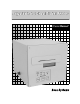
1.0 Introduction The BOCA Adjustable MC Ghost is a direct thermal ticket printer especially designed for airline boarding pass and bagtag applications. The printer will automatically determine if a boarding pass or tag is loaded. Two printers can be daisy chained together in order to print both passes and bag tags from a single host computer. This manual will provide the user with general information regarding printer set-up, configuration and troubleshooting.
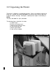
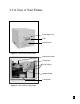
2.0 Unpacking the Printer The printer is shipped in a ruggedized container. Please save packing material for future use. Remove the printer (see figure 1) and accessories from the box and inspect for obvious damage. If damage is noticed please report it immediately to BOCA.
3.
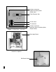
Interface connector, Output to another printer (25 pin male) Ticket Entrance Slot On/Off switch AC connector Figure 4 - Micro Ghost - rear view Interface connector, Input from Host to another printer (25 pin female) Main Logic Board Figure 5 - Micro Ghost - top view with electronics exposed Roll Stock Holder 4
4.0 Installation The Adjustable MC Ghost ticket printer is designed to be mounted on a desktop or on a shelf. Prior to the site preparation and installation, the printer should be posered up and run in the self test mode. Lay the printer flat on a counter as shown in figure 3. Verify that line voltage is the same as the line voltage specified on the serial tag. Attach the AC cord and interface connector into the proper connectors as shown in figure 4. Turn power on. The LCD will display PAPER OUT.
5.0 Configuration The Adjustable MC Ghost is factory configured for a variety of customer requirements. 1. The printer has a resolution of 200dpi. 2. The printer has an adjustable paper path (see figure 7) 3. The printer has a serial interface for input from the host or another printer (see figure 4), and a serial interface for output to another printer. See pinouts in section 6.0.
6.0 Standard Interface Pinouts 6.
7.0 Thermal Paper - Theory & Specification The print head’s life expectancy is composed of both a mechanical and an electrical component. Both of these factors are strongly influenced by the quality of the thermal paper used. MECHANICAL The print head has a theoretical rating of 60 kilometers. This number is based upon the assumption that the head will be used with a good quality, top coated thermal paper.
8.0 Maintenance and Adjustments Your ticket printer is solidly constructed and has been designed for high volume use. It requires minimal care to provide maximum service. This section provides an overview of printer maintenance, including parts alignments, adjustment and replacement.
The position of the tear can be controlled by changing the cut count setting in the OPERATOR MENU (see Appendix A). If you are not able get the desired tear position, then make sure your ticket stock was manufactured to proper specifications. Once a month the opto eye should be blown off with air to remove any accumulated paper dust. A soft haired brush can also be used if air is not available.
8.1.6 THERMAL PRINT HEAD The print head should be cleaned monthly, initially, to prevent debris from building up on the print element. The required cleaning interval varies greatly depending on the quality of the ticket stock and the amount of dust entering the print area. Excessive dirt build up on the print head will result in reduced quality. Continuing to run the print head in a dirty condition will reduce its life expectancy as it is unable to diffuse its heat properly.
Figure 9a - Print Head removal Figure 9b - Print Head removal Figure 9c - Print Head removal 12
8.1.7 Rubber Drive Roller (Platen) The rubber drive roller should be cleaned once a year to prevent paper dust from building up on the roller. Clean drive roller with a paper towel and alcohol. 1. Lift up the cam lock assembly (located above the head mounting block) to remove pressure from the thermal head. (see figure 9a) 2. Lift up the head mounting block/thermal head to remove it. (see figure 9b) 3. Clean the full legth of the Platen. 4. Install the head by reversing steps 1 and 2.
9.
10.0 Troubleshooting Guide This is a simplified troubleshooting guide listing some of the typical problems. It is not intended to provide technical details or repair methods, but can serve as a guide to fault isolation in the field. If you need additional help, please contact BOCA at Tel: (561) 998-9600 Fax: (561) 998-9609 1. NO OPERATION, POWER INDICATOR IS OUT a. b. c. d. 2. Check the power cord for proper installation at both ends. Check main fuse and replace if blown.
5. ERRACTIC PRINT POSITION a. See # 4 6. POOR PRINT OUT (light print out) a. b. c. d. e. 7. Make sure the print head/cam lock assembly if fully locked in the closed position. Consult “Thermal Print Head” in Section 8.1.2. Clean print head. Consult “Thermal Print Head” in Section 8.1.2. Adjust print intensity setting via the control panel (see Appendix A) Replace thermal head. POOR PRINT OUT (white voids in print out) a. Clean print head. Consult “Thermal Print Head” in Section 8.1.2. b.
Appendix A - Operator Menu Options This printer allows the user to adjust various printer options through the control panel. Selects proper menu topic (baud rate, cut count, etc.) Enters new value / Also saves new values. Scrolls through choices in individual menu topics. To access and use the OPERATOR MENU, follow these steps: 1. Ticket stock should be loaded into the printer. 2. Press both MENU and TEST switches simultaneously for about three seconds. The LCD window displays OPERATOR MENU! . 3.
The chart below lists the present menu topics. These topics are subject to change. OPERATOR MENU! BAUD RATE? MINI/MICRO? PRINT SPEED? DIAGNOSTIC MODE? TICKET TYPE? STATUS ENABLED? TRANSPARENT MODE PAPER MODE? INC BPP CUT COUNT? DEC BPP CUT COUNT? INC BTP CUT COUNT? DEC BTP CUT COUNT? PRINT MODE? PRINT INTENSITY? EXIT AND SAVE JUST EXIT The following is an overview of what each Menu option does: BAUD RATE? Controls the serial interface baud rate, parity bit, data bits and stop bits.
MINI/MICRO? Defines the type of printer. MINI Is for a printer with a Silent Cutter Assembly (SC2) ( Mini, Mini Plus, Mini MB, Dual Mini) MICRO Is for a printer without a SC2 (Micro, Micro Ghost, Micro MB, Dual Micro) (factory default) PRINT SPEED? Controls the speed the ticket travels at. Also effects the print quality. The numbers range from 0 - FASTEST to 7 - SLOWEST. 3 is factory default. DIAGNOSTIC MODE? Please consult your Programming Guide Your choices are YES or NO. NO is factory default.
PAPER MODE? Is generally used only for test purposes. It may also be used on roll stock with no black marks on the ticket. Your choices are YES (Enabled) or NO (Disabled). NO is factory default. INC BPP CUT COUNT? Enables the operator to move Boarding Pass tear position to the left (towards the ticket exit area). Cut counts are increments of .005” for 200dpi. The count value is changed by depressing CHOICES. 16 is factory default.
JUST EXIT? Will exit the menu options without saving any changes. If you with to exit without saving the new value then press TEST, if not press MENU. To access and use the SPECIAL MENU, follow steps 1 - 6 under the OPERATOR MENU except press both the TEST and Choice switch simultaneously for three seconds. The following chart below lists the present menu topics in the SPECIAL MENU.