R300 Endurance® by Body-Solid R300 Rower v. 091709 User Manual v.
Table of Contents CONGRATULATIONS..................................................................................3 IMPORTANT SAFETY INSTRUCTION........................................................4 SAFETY GUIDELINES.................................................................................5 - 6 ASSEMBLY INSTRUCTION.........................................................................7 - 19 OPERATING YOUR ROWER.......................................................................
CONGRATULATIONS Congratulations!! Thank you for purchasing your new Endurance Fan Rower. Using state-of-the-art techniques, robust frame structure and superior ergonomic design, Endurance Fan Rower set a new standard for excellence. The Endurance Fan Rower can improve your quality of life by keeping you fit and healthy, increasing your energy levels and enhancing your lifestyle.
Important Safety Instructions Before beginning any fitness program, you should obtain a complete physical examination from your physician. Il est conseille de subir un examen medical complet avant d’entreprendre tout programme d’exercise. Si vous avez des etourdissements ou des faiblesses, arretez les exercices immediatement. When using exercise equipment, you should always take basic precautions, including the following: Read all instructions before using the R300.
Safety Guidelines Successful cardio training programs have one prominent feature in common...safety. Cardio training has some inherent dangers, as do all physical activities. The chance of injury can be greatly reduced or completely removed by using correct running techniques, proper breathing, maintaining equipment in good working condition, and by wearing the appropriate clothing. It is highly recommended that you consult your physician before beginning any exercise program.
Safety Guidelines This exercise equipment is designed and built for optimum safety for home use. However, certain precautions always apply whenever you operate any exercise equipment. Be sure to read the entire manual before assembly and operation of this machine. Also, please note the following safety precautions. MECHANICAL SAFETY Inspect the equipment prior to exercising to ensure that all nuts and bolts are fully tightened before each use.
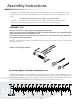
Assembly Instructions Assembly of the R300 takes professional installers about 1/2 hour to complete. If this is the first time you have assembled this type of equipment, plan on significantly more time. Professional installers are highly recommended! However, if you acquire the appropriate tools, obtain assistance, and follow the assembly steps sequentially, the process will take time, but is fairly easy. Assembly Tips Read all “Notes” on each page before beginning each step.
Step 1 Be careful to assemble all components in the sequence they are presented. Note: Do not fully tighten bolts until instructed A.
Step 1 Above shows STEP 1 assembled and completed.
Step 2 Be careful to assemble all components in the sequence they are presented. Note: Fully tighten bolts at the End of each Step. A.
Step 2 Above shows STEP 2 assembled and completed.
Step 3 Be careful to assemble all components in the sequence they are presented. Note: Fully tighten bolts at the End of each Step. A. Lift Up the Main Frame (#1) and Rail Frame (#2), then insert Rail Fram (#2) into the Main Frame (#1). Fit the Shaft (#24) on the Main Frame (#1) into the gap of the Rail Frame (#2).
Step 3 Above shows STEP 3 assembled and completed.
Step 4 Be careful to assemble all components in the sequence they are presented. Note: Fully tighten bolts at the End of each Step. A. Insert the Pull Pin (#98) into the Main Frame (#1) and Rail Frame (#2). B.
Step 4 Above shows STEP 4 assembled and completed.
Step 5 Be careful to assemble all components in the sequence they are presented. Note: Fully tighten bolts at the End of each Step. A.
Step 5 Above shows STEP 5 assembled and completed.
Step 6 Be careful to assemble all components in the sequence they are presented. Note: Fully tighten bolts at the End of each Step. A. Attach Cell Phone Bracket (#20) to the Console Monitor (#19) using Rubber Band (#21). B. Attach the Console Monitor (#19) to the Console Mounting Bracket (#69) using: M8x75mm Button Head Cap Screw (#78), QTY: 1 M8 Flat Washer (#79), QTY: 1 M8 Nylon Lock Nut (#80), QTY: 1 C. Connect Sensor Cable (#23) into the back of the Console Monitor (#19).
Step 6 Above shows STEP 6 assembled and completed.
Operating your Rower MOVING THE ROWER The rower is easy to move around safely. To move the rower: 1. Lift the rear of the rower 2. Roll the rower on its front transport wheels to the desire location. 3. Gently lower the rear of the rower to the ground level STORING THE ROWER The rower can be seprated to minimize the unit size for storage. 1. Remove the Pull Pin (#98). 2. Lift up the Main Frame (#1) and pull out the Rail Frame (#2) 3.
Operating your Rower DAMPER ADJUSTMENT There is a damper adjustment on the right side of the fan Shroud. The indicator can be moved up/down to adjust the damper. #1 is the lowest setting, #9 is the highest setting. HANDLEBAR POSITION Handlebar (#3) can be placed on the hook of the Console Monitor Post (#6) or it can be placed on the Handlebar Holder (#52).
Operating your Rower B. FOOT PEDAL ADJUSTMENT 1. Pull the Foot Pedal (#45) out of the two bulges of the Pedal PEDAL CAP ADJUSTMENT SupportofPlate (#5). CAPS���� can be adjusted. Refer to The position the PEDAL the thethe PEDAL the two bulges 2.illustration. Lower or Pull raised Foot CAP���� Pedal to out thefrom desired location. in the PEDAL SUPPORT���� then lower or raise the PEDAL 3. Lock to thethe Foot Pedal (#45) by pressing the adjustment CAPS���� desired position.
Operating the Console CONSOLE DISPLAY TIME: - Display flashing “00:00” for presetting the TIME program. Time can be set from 1:00 to 99:00 minutes - Displays the time during exercise. STROKE: - Display the total number of stroke during exercise PULSE: - Display the heart rate from 40 to 220 beats per minute during exercise. To use this function, the user must wear the Heart Rate Chest Strap.
Operating the Console CALORIES: - Display flashing “100” for presetting CALORIES program. The target calories value can be set from 10 to 999 cals PADDLE WIDTH: - Display the distance per stroke. STROKE RATE: - Display the current stroke per minute during exerices. DISTANCE: - Display flashing “500” for presetting DISTANCE program. The target distance value can be set from 500 to 9999. CYCLE: - Display flashing “8” for prestting the number of cycle for the INTERVAL program.
Operating the Console ENTER/STOP BUTTON: - Press the button to confirm the value in the program. - Press and hold the button for three seconds to reset the console program. - Press the button to pause the program during workout. INITIAL SETUP POWER ON: - Move the Handlebar or press any button. POWER OFF: - In IDLE mode, if there is no activitiy detected for 20 seconds, the console will shut off automatically.
Operating the Console 1. QUICK START PROGRAM To Quick Start the program, you can pull on the Handlebar (#30) to start. All fuction values fo the console will count up. For the other seven programs, press the “BACK” button to enter IDLE mode. Or press and hold the ”ENTER/STOP” button for three second to restart the console. Use the “SELECT” button to toggle between programs. Use “UP” & “DOWN” Buttons to adjust the value and press “ENTER/STOP” to confirm. 2.
We call this program Score Game, use SELECT button to select the program. The �xed preset TI�E for the game is � minuets, this can’t be changed. Pull on the HANDLEBAR��� to run the program directly. When you complete the program, the matrix display will show your point score and remind you with an audible alarm. Press the BACK button to jump to the IDLE mode. 5. GAME PROGRAM: Operating the Console Hit the four dot block, lose three points.
Monitoring Your Heart Rate Fitness Safety The Heart Rate chart indicates average rate zones for different ages. A variety of different factors (including medication, emotional state, temperature and other conditions) can affect the target heart rate zone that is best for you. Your physician or health care professional can help you determine the exercise intensity that is appropriate for your age and condition. (MHR) = Maximum Heart Rate (THR) = Target Heart Rate 220 - Age = Maximum Heart Rate (MHZ) MHZ x .
Chest Strap Operation Your Endurance® Fan Rower has the capability to determine Heart Rate with the use of a Heart Rate Chest Strap. A Heart Rate Chest Strap can be purchased seperately. It is suggested for the Chest Strap Transmitter that you position the transmitter as close to your heart as possible, against the skin, 1-2 inches below the pectoral muscles. For best results, moisten the back of the transmitter for better contact.
Part List PART# QTY DESCRIPTION 1 1 Main Frame 2 1 Rail Frame 3 1 Handlebar 4 1 Front Stabilizer 5 2 Pedal Support Plate 6 1 Console Monitor Post 7 1 Front Support Leg A 8 1 Front Support Leg B 9 4 Foot Pedal End Cap 10 1 Seat Carriage 11 1 Fan 12 2 Bungee Cord Hook 13 1 Chain Bracket 14 1 Rail 15 1 Perforated Steel Mesh 16 6 Spacer, ø8.2xø12x3.2mm 17 2 Spacer, ø8.2xø12x71.6mm 18 1 Spacer, ø6.2xø10x15.
Part List PART# QTY DESCRIPTION 42 1 Damper 43 1 Right Fan Shroud 44 1 Left Fan Shroud 45 2 Foot Pedal 46 2 Foot Pedal Holder 47 2 Pedal Strap 48 2 Spacer, ø10xø16x30.5mm 49 1 Pulley Spacer, ø10xø16x26.
Part List PART# QTY DESCRIPTION 82 2 Socket Head Cap Screw, M8x40mm 83 2 Phillips Flat Head Screw, M6x16mm 84 4 Socket Head Cap Screw, M8x150mm 85 2 Socket Head Cap Screw, M8x110mm 86 2 Button Head Cap Screw, M8x25mm 87 4 Lock Washer, M8 88 3 Phillips Head Screw, ST4.
Exploded View Diagram 33
Serial Number is Located on the Frame Model Name : R300 Purchase Date: _______________________________ Serial Number: 013438-_______________________ Customer Tech Support Hotline Toll Free: 1-800-556-3113 Phone: 1-708-427-3555 Fax: 1-708-427-3556 Hours: M-F 8:30-5:00 CST E-Mail: service@bodysolid.com 2009. Body-Solid. All rights reserved. Body-Solid reserves the right to change design and specifications when we feel it will improve the product.