BC-7220G PROGRAMMABLE MAGNETIC BIKE 1
INDEX …………………… 1 Exploded-View Assembly Drawing ………………..….. 2 ……………………………………………….… 4 Important Safet y Information Parts List Assembly Instruction ……………………………..…… 6-8 Exercise Instructions …………………………………..… 9-10 Trouble Shooting ……………………………….
IMPORTANT SAFETY INFORMATION Please keep this manual in a safe place for reference. 1. It is important to read this entire manual before assembling and using the equipment. Safe and efficient use can only be achieved if the equipment is assembled, maintained and used properly. It is your responsibility to ensure that all users of the equipment are informed of all warnings and precautions. 2.
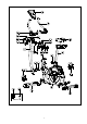
EXPLODED-VIEW ASSEMBLY DRAWING 2
3
PARTS LIST PART NO.
PARTS LIST PART NO. H-4 H-5 H-6 H-7 I I-1 I-2 I-3 I-4 I-5 I-6 DESCRIPTION QTY PART NO. T bar Spring washer (φ7) Screw (M4*40) Screw (M8*16) Front stabilizer Screw (M5*16) Front stabilizer end cap (R) Front stabilizer end cap (L) Rear stabilizer end cap (L) Rear stabilizer Rear stabilizer end cap (R) J J-1 J-2 J-3 J-4 J-5 J-6 J-7 J-8 K 1 2 2 8 1 4 1 1 1 1 DESCRIPTION Idler Wave washer (φ10.5) Bearing Screw (M6*12) Flat washer (φ6) Flat washer (φ10) Flat washer (φ8.
ASSEMBLY INSTRUCTIONS STEP 1 Attach the Front stabilizer (pt.I) and Rear Stabilizer (pt.I-5) to the Main Frame (pt. D) using eight M8*16 Screws (pt. H-7). STEP 2 D-2 D-27 Attach the Pedals (pt. D-1R&L) by screwing them into the corresponding crank arm (pt. D2 & D27). Note that the Right pedal should be threaded on clockwise and the Left pedal on anti-clockwise. STEP 3 Fix the Seat (pt.F-7) to the Seat post (pt.F) as shown, and tighten the bolts around the screws under the seat.
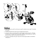
1 2 3 4 STEP 4 1. Release φ8 Washers (pt.C-5), φ8 Flat washers (pt.C-6) and M8*16 Screws (pt.C-7) form Main frame (pt.D). 2. Take the Front post cover (pt.D-16) pass through Front post (pt.C). 3. Connect the Lower sensor wire (pt.D-14) and the Upper sensor wire (pt.C-1), Slide the Front Post (pt. C) into the Front Post Housing, and then fix with two φ8 Washers (pt.C-5), two φ8 Flat washers (pt.C-6) and four M8*16 Screws (pt.C-7). 4. Put down the Front post cover (pt.D-16) to the main frame (pt.
STEP 5 Attach the Handlebar (pt.B) to the Front Post (pt.C) by using clamp (pt.H), fix with one φ8 Flat Washers (pt.H-3), one φ8 Spring Washers (pt.H-5), one M7*30 Bolt (pt.H-1).Pass the pulse sensor wire through the hole. Fit the Rear handlebar cover (pt.C-2) to the Front handlebar cover (pt.C-4) by using one M5*14 Screw (pt.C-3). STEP 6 Connect the pulse sensor wire to the Computer pulse sensor wire. Plug the Upper sensor wire (pt. C-1) into the computer cable box at the back of the computer (pt.
EXERCISE INSTRUCTIONS Using your PROGRAMMABLE MAGNETIC BIKE will provide you with several benefits, it will improve your physical fitness, tone muscle and in conjunction with a calorie controlled diet help you lose weight. 1.The Warm Up Phase This stage helps get the blood flowing around the body and the muscles working properly. It will also reduce the risk of cramp and muscle injury. It is advisable to do a few stretching exercises as shown below.
MUSCLE TONING To tone muscle while on your PROGRAMMABLE MAGNETIC BIKE you will need to have the resistance set quite high. This will put more strain on your leg muscles and may mean you cannot train for as long as you would like. If you are also trying to improve your fitness you may need to alter your training program. You should train as normal during the warm-up and cool-down phases, but towards the end of the exercise phase you should increase the resistance making your legs work harder.
PROGRAMABLE TRAINGING COMPUTER 【BUTTON FUNCTIONS】 UP To make upward adjustment to each function data or increase training resistance. DOWN To make downward adjustment to each function data or decrease training resistance. MODE To confirm all setting. STAR/STOP To start or stop workout. RESET To reset current setting and have the monitor switch to initial training mode for selection. RECOVERY To test heart rate recovery status.
2. Users may use ▲ or ▼ key to select one user profile from U1~U4. SEX, AGE, HEIGHT and WEIGHT are requried to be set. System will enter into the standby mode when all values are done setting. 3. Use ▲ or ▼key to select MANUAL→ PROGRAM→H.R.C.→WATT→USER PROGRAM→MANUAL in circulation order. Press the MODE key when selection is determined. 4. MANUAL – 4-1 Use ▲ or ▼ key to adjust the LEVEL; press the MODE key for confirmation.
7. USER PROGRAM – Users can use ▲ or ▼ key to set PROGRAM graphic. Press the MODE key for confirmation. Press the MODE key for 2 seconds to stop setting. Use ▲ or ▼ key to set TIME; press the START key to start exercise. 8. WATT – WATT default value 120 will be displayed in the alphanumeric column in flashing text waiting for setting. Users can use ▲ or ▼ key to adjust WATT value; press the MODE key for confirmation. User ▲ or ▼ key to set TIME; press the START key to start exercise.
10. RECOVERY – When there’s a heart rate input (under both START and STOP mode); press the RECOVERY key to execute this function. TIME “0:60” will start to count down and the alphanumeric column will display "FX"(X=1~6) when TIME reaches zero. Press the RECOVERY key to return to the pervious awaiting mode. The actual heart rate value will be shown on LCD continually after the test is finished.
COPYRIGHT ©2011 BY BODY SCULPTURE INTERNATIONAL EUROPE LTD. ALL RIGHTS RESERVED. UNAUTHORIZED DUPLICATION IS A VIOLATION OF LAW.